Other Parts Discussed in Thread: TINA-TI
Hi team,
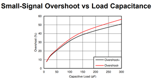
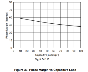
May I ask the maximum capacitive load drive capacity of the TLV9064, can it drive capacitive load that higher than 100pf, such as 10nf(10000pf)?
Thanks!
Regards,
Ivy
This thread has been locked.
If you have a related question, please click the "Ask a related question" button in the top right corner. The newly created question will be automatically linked to this question.
Hi Ivy,
That's a difficult question to answer as it really depends on a set of other conditions such as:
May I ask a few questions:
The more information you provide the better we can support this!
Best Regards,
Robert Clifton
Hi Robert,
Thanks for your reply!
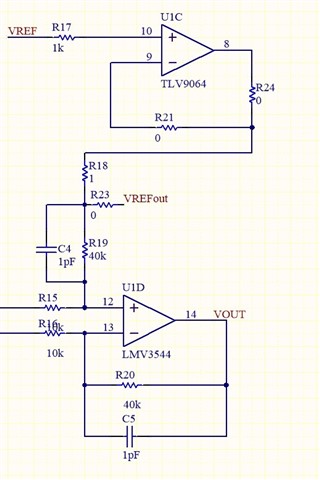
Below is customer's schematic.
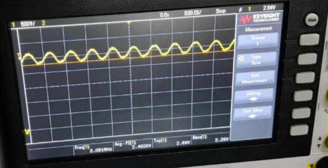
In customer applications, when a 10nF capacitive load is connected to the output of the TLV9064, the output can sometimes be stabilized at 2.5V, and sometimes the output will oscillate randomly as shown in the figure below.(Vref=Vout=2.5V,Vout(p-p) 500mV)
The customer has no specific requirements for gain and phase margin, but expects the output to be stable.
Could you please help give your suggestions about the issue, or whether the TLV9064 can not support 10nF capacitive load?
Regards,
Ivy
Hi Ivy,
Thank you for sharing!
I put this in TINA-TI to see if there's any instability issues. I made some changes to the circuit to make it easier. I changed the supplies to dual supply configuration with 0V on the Vref rather than the single 5V supply and Vref = 2.5V.
Looking at the second stage. It's labeled as the LMV3544, I'm assuming this was also to be a TLV9064. I also assumed that the 10nF capacitor was located on Vout. Please correct me if I'm wrong on that.
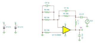
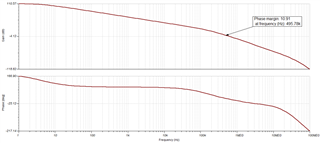
As you can see, the phase margin is 10.91 degrees aka this circuit is unstable. For reference, we recommend having 45 degrees of phase margin to have what's considered a stable circuit.
Is the customer able to make adjustments to their circuit design to add an Riso resistor?
Best Regards,
Robert Clifton
Hi Ivy,
I forgot to add the simulation file.
Best Regards,
Robert Clifton