Other Parts Discussed in Thread: OPA549
Hi there,
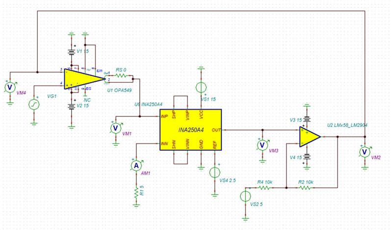
I am trying to create a bipolar transconductance amplifier using the OPA549 as the current driver and the INA250 as shown in the circuit diagram below. The output of the OPA549 goes immediately through the INA250, which measures the current and provides a voltage signal, which is fed back to the inverting input of the OPA549. As the INA250 produces voltage centred around Vin/2, it is necessary to use an opamp to subtract the offset as shown below.
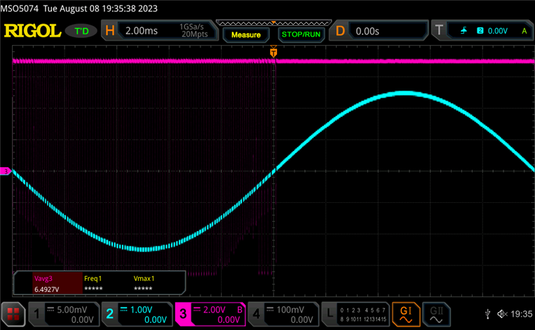
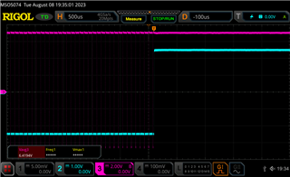
Unfortunately, when constructing this circuit I have found it to be unstable when the input voltage is negative (see oscilloscope measurements). I suspect this is the case due to the feedback opamp's bandwidth being too low relative to the OPA549, but I do not know how to confirm this before revising the circuit. For what it’s worth, I cannot replicate this behaviour in TinaTI.
Any help or guidance would be greatly appreciated. Thanks in advance.

Circuit schematic

Oscilloscope - blue is OPA549 non-inverting input, magenta is OPA549 output


