This thread has been locked.

If you have a related question, please click the "Ask a related question" button in the top right corner. The newly created question will be automatically linked to this question.

OPA2991: the resistor at output pin

Part Number: OPA2991
Other Parts Discussed in Thread: TINA-TI, LM2902, TMS320F28377D

Dear expert

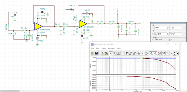
My customer is using OPA2991. Below is the schematic they are using. 

Customer simulated the Bode plot with different resistor(at the output pin of U3) with TINA-TI (see the 1st figure). They found that the bandwidth is 7kHz at 2kΩ and 14.37kHz at 100Ω. They also carried out the experiments. And the results are totally different with simulation. According to the test, the bandwidth is always 42kHz in both 2kΩ and 100Ω. (see the 2nd figure)

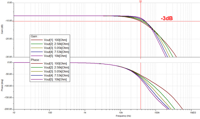
(1) Why the results of the simulation were inconsistent with the experiment? I also simulated the same circuit in TINA to verify their simulation results (see the 3rd figure, R7 is the resistor). the bandwidth are 40.86kHz when R7 is 2kΩ and 37.37kHz when R7 is 100Ω. 

Could you please check the circuit and explained the influence of the R7 on the bandwidth?  Why my simulation result is different with the customer's and different with the experimental results? which result is reasonable? 

(2) another phenomenon is that the customer's schematic has some difference with the circuit they simulated in TINA. In the customer's schematic, the test point TP6/7 is set on the input side of the Pi type filter, but in the TINA circuit, the output seems set on the output side of Pi type filter. (see the 4th figure for more detail)

I'm not sure if that's why the experimental results didn't match the simulation. So I changed the circuit in TINA to make it consistent with the actual schematic, in which the output was set on the input side of the Pi type filter. and the results is 39.12kHz when R7 is 2kΩ and 33.57kHz when R7 is 100Ω. (see the 5th figure) obviously, the resistor also affect the bandwidth and the simulation results still don't match the experimental results.

Best regards,

Rannie

  • Hi Rannie, 

    First of all, I noticed they are using the LM2902 in the customer TINA simulation rather than the OPA2991. Could you clarify which part they are using for the measurements and that it correlates with the simulations? 

    There also looks to be a difference with the supply voltage in the first schematic and the simulation (+/- 15V versus +/-12V). Which one was used for the measured results? 

    Best Regards,
    Ashley

  • Hi Ashley,

    Thanks for your reply.

    The customer tested the bandwidth with a big signal input (large than 1V). Is the bandwidth simulated in TINA based on the small signal input? If it is, is this the reason that the simulation results don't match the test results?

    For the op Amp circuit, how do we measure the bandwidth? 

    Best regards,

    Rannie

  • Hi Ashley,

    In the customer's real schematic, there is a DSP connected to the output in the schematic between the Vout and GND. The R10 is set as a replacement load for DSP. Is this equivalent reasonable? or How will the bandwidth be affected when the output is connected to the DSP.

    Best regards,

    Rannie

  • Hi Rannie, 

    We recommend to not include R7 in this configuration as it impacts both bandwidth and stability. Please see the following thread for the explanation: https://e2e.ti.com/support/amplifiers-group/amplifiers-internal/f/amplifiers-internal-forum/1262333/lm2902-resistor-at-output-pin

    Could you explain why this resistor is necessary for this customer application?

    Connecting to a DSP on the output would be seen as a capacitive load. But this should be in the range of pF and negligible considering there is a nF capacitor in parallel that will dominate the capacitance. You can still simulate it to see the effects but it should not impact the overall behavior. The main contributor is R7 that is impacting the bandwidth and stability as mentioned previously. 

    Please let me know if you have further questions.
    Thank you!

    Best Regards,
    Ashley

  • Hi Ashley,

    Thanks for your supports.

    Actually, R7 is inevitable in the customer's system. 

    There is a question about the test. For the op Amp circuit, how do we measure the bandwidth? The customer also want to test the bandwidth of this circuit to see the influence of this resistor. 

    Best regards,

    Rannie

  • Hi Ashley,

    Actually, they used the R7 to reduce the drive capability of the OPA2991. In their schematic, the output is connected to the ADC input of TMS320F28377D. The resistor R7 is used to limit the output current of OPA2991.

    Best regards,

    Rannie

  • Hi Rannie, 

    To test bandwidth, they can perform what they were showing in the oscilloscope image earlier. You would need to find the frequency at which the output voltage is at the -3dB point (or 0.707V if you are using a unity gain configuration and input signal is 1V) and that would be your measured closed loop bandwidth. There is some limitations depending on the resolution of the oscilloscope they are using, so simulation would be better if they are looking to see the impacts of resistor changes. 

    If R7 is to reduce output current, one option is to put the resistor outside of the feedback loop. As mentioned previously, having the high value resistor in the feedback loop will limit the bandwidth and impact stability.

    Please let me know if you have further questions.
    Thank you!

    Best Regards,
    Ashley

  • Hi Ashley,

    Thanks for your supports, it's really helpful.

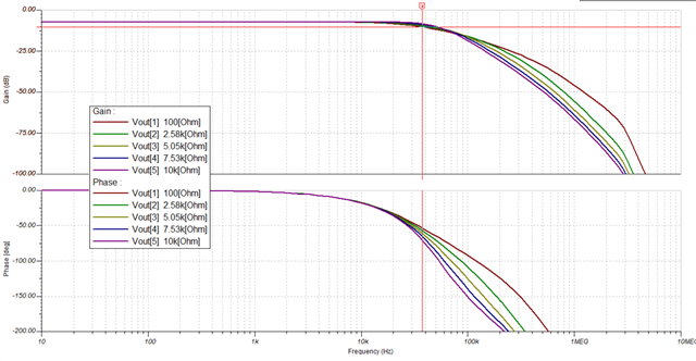
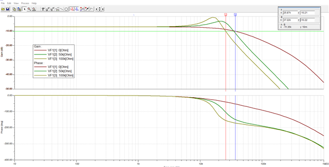
    I simulated in TINA and swept the R7. The results are shown as follow. The simulation results show that the relationship between the -3dB bandwidth of the system and the resistor seems unclear. 

    According to the customer's test results, the -3db bandwidth is not changed with 2kΩ and 100Ω.

    Best regards,

    Rannie

  • Hi Rannie, 

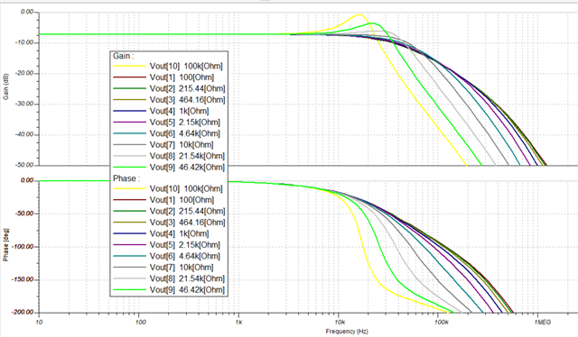
    If you compare two points at the extremes with different resistor values for R7, you can see the differences at -3dB bandwidth, with a difference between 25kHz and 37kHz for 0ohms and 100kohms respectively.

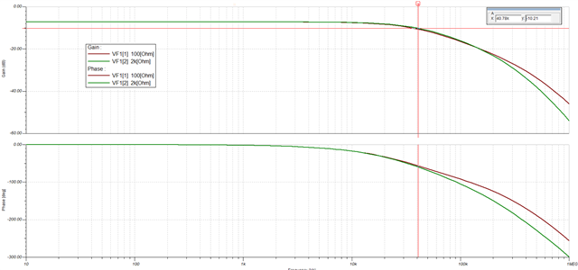
    Simulating between 100ohms and 2kohms, the closed loop response looks very similar for the circuit, which may explain why the customer did not see any difference in their testing. Did the customer test the full circuit or partial? 

    Please let me know if you have further questions.
    Thank you!

    Best Regards,
    Ashley