This thread has been locked.

If you have a related question, please click the "Ask a related question" button in the top right corner. The newly created question will be automatically linked to this question.

INA228: Current measure error

Part Number: INA228

Hello,

I'm trying to measure current and bus voltage with INA228 monitor. Since current in the load could reach up to 100 A (peak), 300 uOhm resistor (CSS2H-5930R-L300F) is used as a shunt resistor. With ADCRANGE=1 such resistor value is capable for currents up to 136.5 A, with ADCRANGE=0 maximum current can be 4 times higher.
As a load during testing I used electronic load device (B&K Precision BK8614) which has (of course) capability to select desired current that will flowing in to the load.
However, regardless ADCRANGE=1 or ADCRANGE=0 is used, I get the simillar "wrong" measurements:

Current to the electronic load (A) Current measured with INA228 (A)
1 1.00
10 9.47
20 18.89
30 28.32
40 37.78
50 47.30
60 56.77
70 66.31

As you can see, INA228 gets smaller values of current than actual are. On the other side, VBUS voltage is measured correctly always.

I tried to change resistor and after that measurements are more accurate (for ex. at 10 A INA228 now shows that current equals 9.77 A, ... ) but there must be also other circumstances which have an affect on measurements.
A schematic is below:
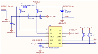
As you can see on schematic - C5 and C6 capacitors are not placed. They could be used to surppress common mode noise. Do you think that this could help? What about resistor and capacitor values of differential mode filter (R2, R3, C4)? Do you suggest to change values of mentioned components?

And belonging layout is below:
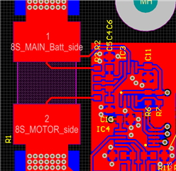
Any idea what could be reason for such measurement error?

Many thanks,
Kind regards,
Dejan.

  • Hello Dejan,

    Looking over your data, it is most likely that the e-load is not giving the exact current you expect. I recommend measuring the voltage across the IN+ and IN- pins of the INA228 to verify that the shunt voltage reading is the same as the measured voltage. It would also be a good idea to measure the resistance of your shunt to confirm it is what you expect after being soldered onto the PCB. Also, make sure that C5 and C6 are not populated, which looks to be the case.

    Regards,

    Mitch

  • Hello Mitch,

    thanks for your reply. Electronic load is calibrated, so I'm sure that it works fine.
    It looks like that a reason for the error I'm getting is voltage drop over shunt resistor pads.
    As you can see from the layout picture above, I'm measuring voltage drop on the internal side of resistor pads. At 50 A INA228 has 14.6 mV between IN+ and IN- pins. The same voltage I get if I use portable voltmeter and measure voltage on the same points on the resistor. If I measure voltage drop on the external side of the shunt resistor, there is a 15.6 mV of voltage drop. The right value would be 15 mV, since 3 mOhm x 50 A = 15 mV.
    It looks like that one option would be that I make a "hardware" calibration (move IN+ and IN- traces to the right point on the shunt resistor pads), but this seems less logic option since 4-wire method is now used, and another option would be "software" calibration which sounds more appropriate.
    What do you think?

    Kind regards,
    Many thanks,
    Dejan.

  • Hello Dejan,

    From the information you gave above, it looks like the primary issue in the hardware. The most likely causes of this is solder joints to resistors, or imbalance in R2 and R3. It is good that you are using Kelvin connections to the shunt, so I would not change those to the outsides of the resistor. If you want to improve your shunt connection, then you could switch to a 4 wire shunt that has dedicated connections for shunt measurements. In either case, you'll need to make sure that your solder connection has as low resistance as possible, as your shunt has such a small value. You may also want to try temporarily removing (shorting) R2 and R3 to see if that improves the measurement. You can calibrate this with software, but it may be a good idea to get as good a hardware setup as possible before relying on software. Here are a couple videos that can help you with this:

    https://www.ti.com/video/6076326896001

    https://www.ti.com/video/6243578140001

    Also, I highly recommend verifying the current on the line and comparing that to the measured value of the shunt, since the INA228 is showing you the correct measurement. 

    Regards,

    Mitch