This thread has been locked.

If you have a related question, please click the "Ask a related question" button in the top right corner. The newly created question will be automatically linked to this question.

OPA320: Output does not match magnification

Part Number: OPA320

sample.pdf

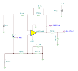
The amplification factor is 1.65, but when the input of opa320 is 0.18V, the output is 0.55. The operational amplifier bandwidth, device soldering, and stability of the power supply have all been checked to be normal, and the chip has not generated heat. Could you please provide your opinion? What may be the problem?

  • Zhang,

    Your circuit is called a "diff-amp".  It's gain is calculated as Rf/Rg = 3.3k/10k = 0.33.  For a differential input of 0.55, the expected output is (0.55V)*(0.33) = 0.182V.  You can simulate this circuit as well.  See below the result of a simulation for the DC operating point.  I also attached the TINA SPICE schematic.  Doing simulation is a good way to check to see if your circuit is operating as expected.

    dif amp.TSC

    I hope this helps.  Best regards, Art

  • 8585.sample.pdf

    Could you please help me check if the PCB is reasonable? Now adjust the magnification, and the output does not follow the change.

  • Zhang,

    Based on your initial measurements, your circuit was working as expected.  That was the point of my last post. 

    The new configuration does not follow the normal design of a differential amplifier.  For a differential amplifier the resistor network connected to the inverting and non-inverting input match.  Your feedback resistor is 3.3k, but your non-inverting input has a 16.5k resistor to ground.  This is not a normal differential amplifier and will not have the differential gain of Rf/Rg.  If you want a traditional diff-amp, you will need to change the resistor on the non-inverting input from 16.5k to 3.3k.  

    The circuit as currently designed will have a gain of Vout = Vin_non*(10k/(16.5k +10k))*(3.3k/10k +1) + Vin_inv*(- 3.3k/10k).  Basically the non-inverting input is divided by a voltage divider than gained by the non-inverting gain relationship.  On the inverting input the gain is simply -Rf/Rg.

    If you change the circuit you can use TINA spice to predict the output.  TINA is a free simulator that allows you to set the input voltage and simulate the output voltage using "Analysis>DC analysis>calculate nodal voltages".  To trouble shoot your physical circuit you will need to confirm: the input voltages, the power supply voltages, and the output voltage.  For the power supply you are just confirming that the supply is connected.  Since your original circuit functioned correctly, I think your hardware is fine.  I think it is likely that your expected voltage is calculated incorrectly.  Just use Tina or the equation above.

    Best regarrds,

    Art