This thread has been locked.

If you have a related question, please click the "Ask a related question" button in the top right corner. The newly created question will be automatically linked to this question.

THS3491: Device dies

Part Number: THS3491

Hi

we are facing an issue on the THS3491IRGTT device. For some uknonwn reason the device dies.
We are sure that the problem is not short-circut to ground becaue we have already tested it and the device recovers.

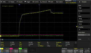
When the device is working properly we have this behaviour..
I apply a 10V step and we have a very fast rise time

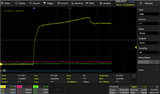
When the device stops working we are facing this behaviour

Another behavior is that the current capability decrease to few mA

Whic critical conditions can happen to destroy the device?

  • I have this problem with low ohmic load ( about 22Ohm - 2.2V )

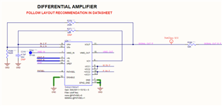
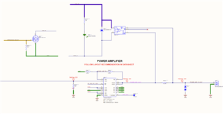
    I attach also the schematic part how we drive the frontend

    What can be the problem that causes the partial die?

  • Hi Alessandro,

    Thank you for providing the snippets you provided. I did have some questions about the design and the input/output signals of the device. Is the yellow 10Vpp signal measured at the output of the THS3491 at pin 10? Or is it the input signal measured at pin 4? You mentioned you applied a 10V step, so I was curious if the signal measured in channel 1 is the input signal you're mentioning. With the 22-ohm load, what is the expected current output of the device? Also, when the device breaks, does the device fail after some time outputting a signal or is it an instant failure when an input is applied? 

    Best Regards,

    Ignacio

  • The Yellow signal has been measured in the output of THS3491.
    Looking at the second picutre, you can see a connector after 50Ohm resistor. The signal is measured there.

    Let me give a little overview about the test(s) we do where the device breaks:

    1) I apply a 10Vpp step without load ( only oscilloscope probe ) and the device responds properly with a fast rise time

    2) Some DC tests where the output is closed on different load by external mechanical relay.
        In particular one of these DC tests apply about 2V2 DC on a 22Ohm load to drive about 100mA.

        Somehow and for unknow reason the device breaks during the test(s) at number 2.

    3) i repeat the test at number 1 and I discover the deivce breaks.

    Basically it seems the internal circuit looses the max current capacilbitiy. It's partially died.

    I verified the device is protected against the short circuit becuase I applied a square wave 10Vpp and I shorted to ground the ooutput.
    After release the short the square wave appears again.

    What could be the main reason(s) for the device breaks?

    Regards

  • Hi Alessandro,

    That is interesting the device is dying with 2.2V at the output with a 22-Ohm load. I have a couple troubleshooting suggestions. Is there a way to run test 2 prior to test 1? So, running the test that is breaking prior to any relay switching. Another possible test to debug this, if possible, would be to connect a 22-Ohm static load and apply the expected input and probe the output. We are trying to rule out if the issue is the test configuration itself or some external reason this is occurring.

    Best Regards,

    Ignacio

  • Hi Ignacio

    please ignore step 2 of above mentioned test(s).

    We are facing the same issue in different test cases and we are not sure that the 22Ohm load causes the problem also becuase sometimes the test passes without problem.

    In you experience what could be the possibile causes that can destroy the device?
    I remind you 2 things:

    - we already test the short-circuit protection and the deivce recovers properly.

    - we see the device is not totaly died, but it's partially died becuase the max current is quite low ( about 20-30mA )

    if you have some ideas we can check better the hrdware and firmwaare if we do not properly configure the device.

  • Hi Alessandro,

    Thank you for the information. When you do have a device that partially dies. Have you tried shutting the device off for some time say 10 minutes to cool down then trying a test again? The device might be going into thermal shutdown mode but might still work once the device is shut off and allowed to cool down and basically reset.

    Best Regards,

    Ignacio

  • Hi Ignacio

    10x for your feedback.

    I supposed thsi problem too, but I excluded it because even if I wait for 2-3hours the device does not recover it.

    I see in the datashee that the Max Output continuous current is +/- 100mA.

    What exacltly this parameter says? During short circuit we have more than 100mA and the device seems recover properly.

    For sure during some test the OpAmp drives a little bit more than 100mA

    Regards

    Alessandro

  • I tried to set up 7.5V on the output and drive up to 270mA continuosly for more than 1minute without problem.

  • Hi Alessandro,

    The continuous output current abs max rating is the continuous RMS current the device can output without electro-migration occurring. This spec applies to a long-term condition (in the years range) where the device will not be turned off. A little more than 100mA should not push be pushing the device to much. Is there a way to run these tests without the relay? Assuming your input/output voltage ranges are within the recommended ranges and you're not pulling excessive amounts of current, the device should not be getting damaged. 

    Best Regards,

    Ignacio

  • Ok Understood

    The continuous output current abs max rating is not the current case.

    My test(s) take some seconds.
    Remember that the device partially sources current but not fully and I recognize also from the rise time

    What other reason could occur to break the device?

  • Hi Alessandro,

    Could you remove the mechanical relay at the output and run the tests with passive components in the configurations that you are running. One concern is the relay at the output, by running these tests and isolating the device we can confirm whether it is the device or the relay causing these issues.

    Best Regards,

    Ignacio

  • Hi Ignacio

    I was able to reproduce the problem that cause the problem.

    Step1 =>>>> OpAmp => directly shorted to ground
    ------------------------------------------------
    I apply a 10V step pulsing shorted to ground
    The device goes in pretection mode and as soon as i remove the short it recovers properly

    Step2 =>>>> OpAmp => switch + 2Ohm serie resistor => Load **************************
    --------------------------------------------------------------------------------------
    One of the test case introduces a discrete mosfet switch in between front-end output and load.
    So we have: OpAmp => switch + 2Ohm serie resistor => Load(5R6 and lower )

    I apply 3V on 5R6 load.
    As you can see from the yellow and purple signal they go to zero and after a while it tries to recover and periodically does this.

    Purple signal is the front-end output
    Yellow signal is on the load

    To Better confirm this, I tried cooling the component down with freeze air and the behaviour disappears temporarely and appears again after a while.
    This sounds good.

    Step2 =>>>> OpAmp => switch => short to ground
    ------------------------------------------------
    As soon as I create a short circuit on the load I have this

    and after I restore to 5R6 we have this

    as you can see, the frontend starts oscillating (purple signal).

    Step3 =>>>> OpAmp => disconnected from all
    -----------------------------------------------------------
    As soon as I remove the switch in the middle of path and apply a 10V stepping pulse it seems the device lost the current capability
    Even if I cool down the chip and power down the system for a while the chip does not recove it


    Is it posssible that during STEP2 ( OpAmp => switch + 2Ohm serie resistor => Load )
    the device dooes not enter in short circuit protection because it sources a big current,
    but still lower than protection threshold and so this cause the partially destroying front end output?

    What other possibile reasons can cause the damage?

  • Maybe a fast mismatchin impedance due to the high current request causes an oscillation of the front-end output and the protection featured does not intervene??


  • Hi Alessandro,

    Thank you for the information you provided. I will speak to a designer on our team that can offer some insight into the short circuit protection circuitry and if there are any obvious reasons the device is behaving this way. I did have some questions regarding some of these tests. For the first test involving the switch with the 5R6 load, how much current is the device outputting through that load network? When you cooled the device down and it worked better that is most likely a sign the device is being pushed beyond its capabilities. The second question I have is if you are seeing any oscillations at the output of the THS3491 when you initially have the switch with the 5R6 load or does the oscillation only occur when you start the setup with the switch+shorted output then change to the switch+5R6 load configuration.

    I was also wondering if you could maybe zip the images or put them in a word doc as for some reason we cannot see them directly on the thread. This will be useful in understanding what the device is doing.

    Best Regards,

    Ignacio

  • Hi Ignacio

    here attached the doc requested

  • Hi Ignacio

    the browser does not allow me to attach any valid file. ( I do not know why )

    I sent you may email alessandro.feriani@n-plus-t.com

    If you reply me from you email accont I can attach the file there.

  • Hi Alessandro,

    I sent you a private message to see if attaching any files through there will work.

    Best Regards,

    Ignacio