This thread has been locked.

If you have a related question, please click the "Ask a related question" button in the top right corner. The newly created question will be automatically linked to this question.

TL074: TL074ACN

Part Number: TL074

I am using TL074ACN  for the voltage sensing 600v and design is as given below.
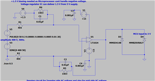
At the controller input and opam output, the noise is very much high.

we  tried to remove it  through the RC filter   but it is not significant. the value of r is 10 ohm and c is 1000micro faraday.

1. Apart from the digital filtering, what are analog circuit we can use for the filtering the noise?

Please help us through the possible solution for filtering the noise

  • Hello Nitish, welcome to the e2e forums.

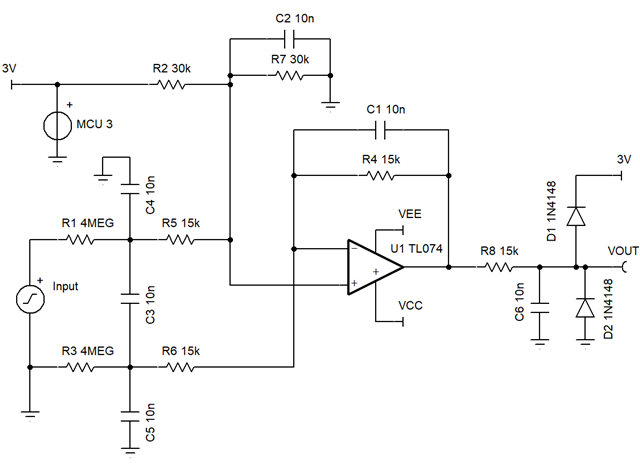
    The simple input filter reduces noise. I added a filter to output also. Added benefit is that output current for over range is much less than direct Zener. 

    The 1.5V offset can derived from the MCU 3V.

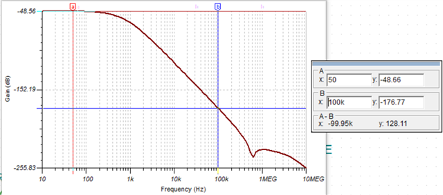
    50Hz Gain is -48.66dB (divide IN by 271) and 100kHz gain is 127dB down from 50Hz gain 

  • Thank you so much for the help; I have some more queries
    If we want to measure the DC voltage(0 to 600v) without offset, what modification will be incorporated in your suggested circuit?
    1. Can any filter circuit be incorporated to filter the noise at the output directly?

  • For a unipolarity input, the offset can be set to 0V, so remove R2 & make R7 15k. Output would be IN / 271 + 0V so full range (600V) is 2.21V output. For less over range capability, increase R4 and R7 and/or decrease R1 & R3

    For filter design see this online tool; https://webench.ti.com/filter-design-tool/

  • Thank you so much for your help and support

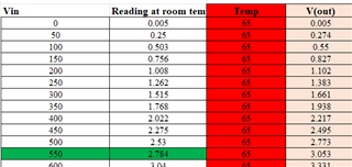
  • The opam we are testing at different temperature and its value is changing, how temperature effect can be compensated in the circuit you suggested. we are testing this opam at 25 celsius and then 65 degree.  I am attaching the data at different temperature

  • Nitish,

    25C equation is y = 5.1mili X - 1.6mV

    65C equation is y = 3.2mili X - 3.2mV

    The 1.6mV offset change is small. The gain change is big. The gain is set by the 4M resistors versus the 15k and 30k resistors.

    Are all of these resistors at the same temperature?

    How many resistor are used to make the 4M resistance? Voltage modulation and it's temperature coefficient may play a factor.

    If you chart the voltage on the non inverting input (the input signal), you will see the same loss in gain as seen in the output. The resistors are the reason, they need to have the same temperature coefficient, the lower the better.