This thread has been locked.

If you have a related question, please click the "Ask a related question" button in the top right corner. The newly created question will be automatically linked to this question.

OPA277: Signal conditiong and offset

Part Number: OPA277
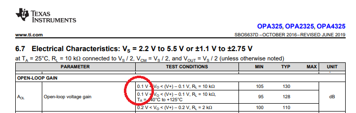
Other Parts Discussed in Thread: OPA364, OPA4325, OPA4277, OPA325

 I am planning to measure the 12 current from different hall sensors. The fundamental current the hall sensor is 400Hz  and have harmonics upto 15KHz. The hall sensor converts the current signal to instantaneous voltage signal varies between +/-5V, which I want it bring to be connected to the microcontroller board. The analog signals must between 0 and 3V.

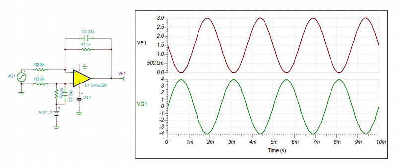
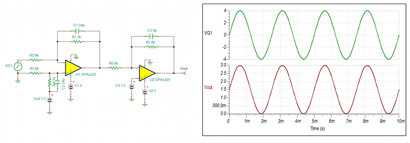
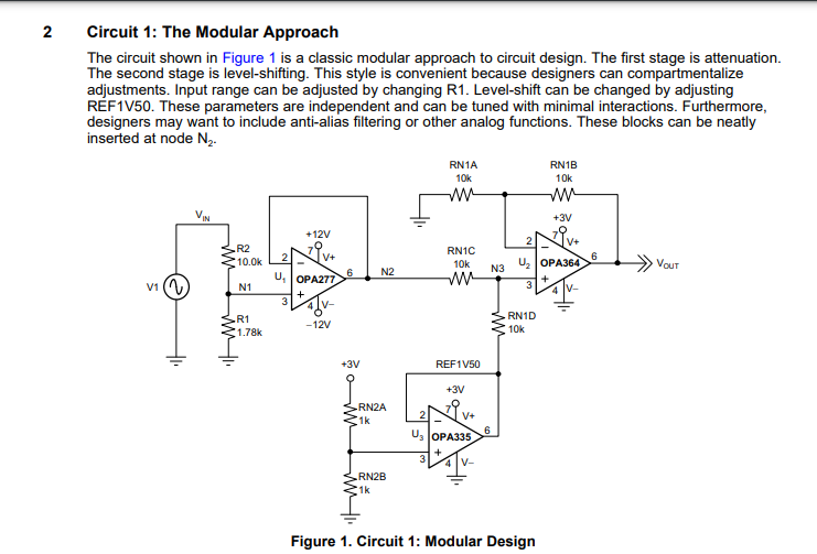
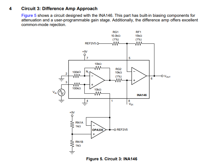
To connect to the microcontroller I am using the classic approach, that is, first the signal(between +/-4V) is to be scaled to +/-1.5V, and then add 1.5V offset to the signal to get it in the range of 0 and 3V. It is said in the TIs document to use different IC for the two stages. OPA277 is suggested for the first stage, and OPA364 is recommended for the second stage.

I have two concerns. First, I don't want to use too many components . So, I want to use a single quad IC for both the stages. However, one would say, we could process 2 signals in a quad opamp using 2 set of opamps, and we can use both the series keeping the number of ICs same. I am worried about the cross talk. Furthermore, I am concerned about the reliability. If an IC fails both the currents would be unavailable.

Please suggest me an IC that can work for both the stages. My requirements are descent bandwidth, fast response.

Regards, 

Rajesh BN.

  • Hi Rajesh,

    What you describe may be accomplished using a singe channel of OPA4325 - see below.

    If you cannot handle output signal inversion in software, you may add the second stage to invert the signa around 1.5V reference voltage - see below.

    Keep in mind, however, that no op amp output may get all the way to its negative rail. Even though OPA4325 output may swing within 10mV of negative rai, its linear range is specified in AOl to be 0.1V above ground and thus any signa closer than that may be distorted - see below.

    OPA4325 4V to 1.5V Sensing circuit.TSC

  • Dear Lis,

    We have several circuits to realize the application I described above as mentioned in the TI's document provided. However, I have few fundamental doubts. As far as noise immunity is concerned, using bipolar based OPAMP  has any benefits over uni-polar circuit?

    Secondly, Why cant I use the same OPA277 for scaling and offset as given in Circuit 1 in the document provided below. Anyways,  I am planning to use a voltage follower circuit at the final stage which share the same voltage of micro-controller's analog power supply(3.3V).

    TI reference designs for signal conditioning to feed ADC

    Regards,

    Rajesh BN.

  • Hi Rajesh,

    I believe there is some disconnect within the naming nomenclature you use - bipolar op amp typical refers to bipolar input transistor while you most likely mean by this dual supply.  Having said that, assuming you properly decouple the power supplies (with caps), there should be no difference in noise performance between singe vs dual supply.

    Whether you may be able to use OPA277 alone depends on the sampling frequency and thus acquisition time required by your system - in the Circuit 1 shown below, OPA277 provides front-end precision scaling while OPA364 allows fast sampling rate by ADC.

    My suggestion of circuit using OPA4325 has to do with the fact that it is CMOS op amp with 100x lower current noise and 10x higher GBW than OPA4277, which translates into superior ADC drive capability and for all practical purposes is a version of Circuit 3 shown below.  Also, OPA4325 is about 5 times lower cost than OPA4277 ($0.95 vs $4.57, respectively).  But the choice is all yours.

  • Hi Lis, 

    Sorry for the confusion regarding 'bipolar' and yes I meant dual supply. What I understand is, first OPA325 has an edge over and is best substitute, however, does the IC is rated for +/-5V? I could see +/-2.5V in the datasheet. I believe if OP325 can be used for boy the stages if it can take +/-5V.

    Regards,

    Rajesh BN.

  • Rajesh,

    Yes, OPA325 is specified for 5V single supply or dual +/-2.5V.  However, since your application output requires only 0V to 3V range, there is no need for +/-5V supplies as shown above on my first reply schematic - only left side of R2 and R3 sees higher voltage but not OPA325 itself.

  • Hi Lis,

    I want to use 2 stage processing, for I can have an independence between varying the signal pk-pk amplitude and adding offset. In this case, which OPAMP would be better to use for both scaling stage and offset stage? Anyways, I will use OP325 as a final stage, as u suggested that the opamp connected to the microcontroller analog pin is supposed to be fast.

    Regards,

    Rajesh BN.

  • Rajesh,

    If you want to use just one type of op amp, I would use OPA4325, which is specifically designed for driving ADC's inputs.  Btw, don't forget to include RC filter in front of ADC.

  • Hi Lis,

    The capacitor that is connected across the feedback resistor is mandatory, though the opamp just does a scaling?

  • The feedback capacitor is there only for stability to cancel zero created by the internal input capacitance Cin=Cin_diff+Cin_cm=5pF+4pF=9pF.  To assure stability: Rin*Cin= RF* CF   

  • Thank you for the explanation. By the way, how do you get those capacitance, Cdiff and Cin_cm? I searched for common mode capacitance and differential capcitance, but I would not find.

    Regards,

    Rajesh BN.

  • Here they are:


    Regards,

    Marek