This thread has been locked.

If you have a related question, please click the "Ask a related question" button in the top right corner. The newly created question will be automatically linked to this question.

LM2904B-Q1: What is the range of values ​​for the bias resistor and feedback resistor?
Part Number: LM2904B-Q1
Other Parts Discussed in Thread: LM2904B

Hi team,

What is the range of values ​​for the bias resistor and feedback resistor?

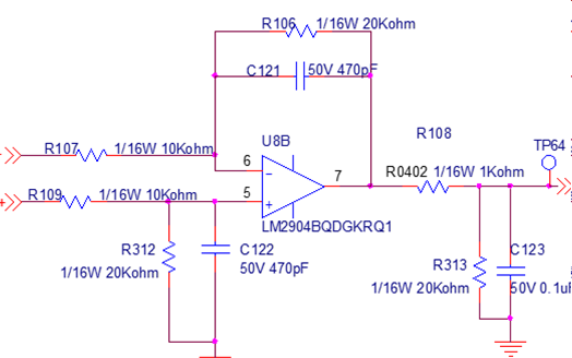
The increase in the resistance of R106 and R107 can effectively suppress Vos. However, the increase in resistance itself will also cause noise. Therefore, what is the range for choosing the resistance values ​​of R106 and R107? Will there be a problem if I use 100k and 200k?

Thanks!

  • Hey Guohai,

    The performance of a difference amp degrades as your impedances have worse matching. You can simulate the effects of your passive components in a SPICE simulator like PSpice for TI or TINA-TI. A better way to cancel offset is to apply a small dc voltage (usually done with a DAC) to your non-inverting node through R312. Also, offset voltage can occur in either direction, was the plan to change R106/107 or R109/R312 on a case by case basis to use input bias current to cancel the offset voltage? That approach does not scale well.

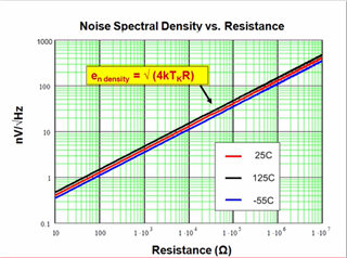
    As for noise, the importance is that the resistor noise does not become a dominant factor in your system. You can calculate your noise by hand with the methods in the following video: https://www.ti.com/video/4078839879001, or you can simulate it with the methods in the following video: https://www.ti.com/video/4080198391001. As a rule of thumb, your resistor noise spectral density will follow the below trend, but going from noise spectral density to output noise can get a bit convoluted. The easiest way to see what your output noise will be is through simulation, or through the Analog Engineer's Calculator. These tools will help weigh what is your best option for your application.

    It can be hard to set a benchmark for best component values, as this varies from application to application. Please let me know if you have any further questions on the above design resources.

    Best,
    Jerry

  • Hi Jerry,


    What will be the impact if R106 and 107 change from 10K and 20K to 100K and 200K?

    Thanks!

  • Guohai,

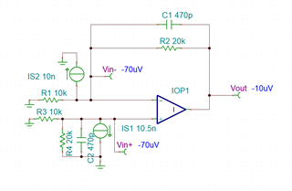
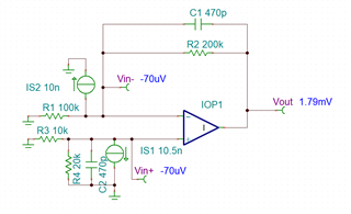
    If R106 and R107 increase by 10x, your equivalent parallel impedance on the input of the pin increases 10x. So your current noise would increase by a factor of 10, and your bias current error would increase. Since the impedances on the inputs no longer match, your input bias current error is now your dominant error source. You can see this in simulation below. I have used an ideal amplifier to show only the error from the bias current. In your circuit, you will have the offset voltage, common-mode error, power-supply error, and other nonidealities. This simulation is just to show a single error source and how changing the impedance will change the error.

    With the LM2904B standard input bias current of 10nA and input offset current of 0.5nA, 10uV of error on the output can be seen. Since your input errors are equal but opposite, they cancel out.

    Increasing R106 and R107 (R1 and R2 in the schematic) by 10x, we now see an extra 1.79mV of error on the output. This is a 179x increase in input bias related error.

    For the difference amplifier architecture, it is important to match resistances on the inputs. Mismatches can cause large increases in error.

    Best,
    Jerry