This thread has been locked.

If you have a related question, please click the "Ask a related question" button in the top right corner. The newly created question will be automatically linked to this question.

INA851: Simulation TINA for TI

Part Number: INA851

Hello,

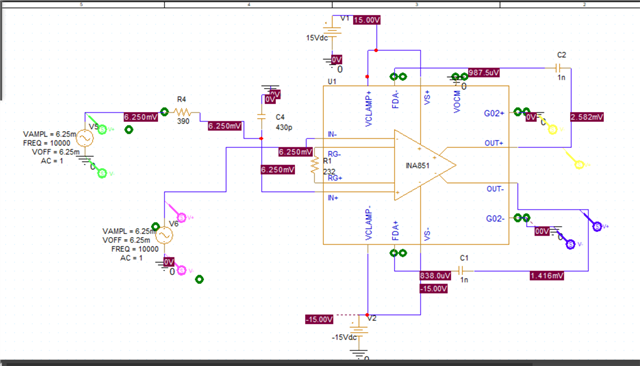
I am getting strange voltages in my simulation for the INA851 amplifier. I am trying to simulate a differential signal with an amplitude of 12.5mV on the left side of my circuit. I expect an amplification of 26.86 due to the 232Ohm resistor, so all in all the output voltage should be 335.7mV. However, the output voltages are only half that. Is this because I have a differential output and if so can I just connect the outputs in an analog to digital conversion and the voltage will automatically double internally? Or did I miss something in my simulation?

Thank you so much!
  • HI Micha,

    In the real INA851 device, when using the input stage in gain of ~27.86V/V (1+ 6kΩ / 232Ω), and the gain of the output stage configured at G=1, the G02- and G02+ pins need to float, and these pins should not be grounded. 

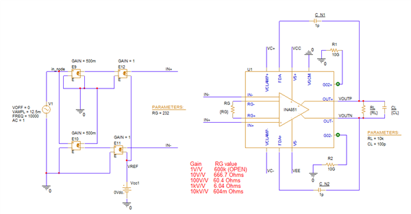
    I noticed that the simulator issues an error when leaving the G02+ and G02- pins floating.  One simple workaround  is to connect the G02+/- pins to a high value 10GΩ resistor to GND to eliminate the simulation error, where the G02+/- pins are essentially floating.

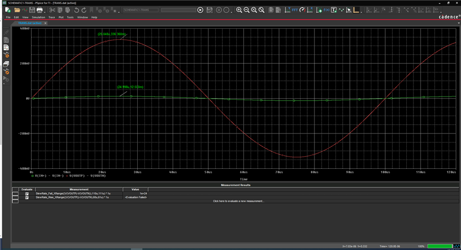
    Below is the circuit and transient results, showing output of ~336mV pk for a ~12.5mVpk input.  Also attached is the INA851 PSPICE project.

    I should mention, this is still a preliminary INA851 model that is in the queue for an update soon, but most circuits work properly.

    Thank you and Kind Regards,

    Luis Chioye

    Modified INA851 PSPICE project:

    ina851_test_forum_9-15-23.zip

    Schematic:

    Transient Result

  • Hi Luis,

    thanks for the quick respond. 

    Your scoped Output is defined by V(IN+) - V(IN-). So just the V(IN+) is half of the 336mV around V(IN+) = 168mV. Thats the same like I got in my simulation. 

    Unfortunately, I have not yet had much to do with differential signals, so I wonder if it is normal that I have to subtract both outputs from each other to get to the actual fully amplified signal. And if this subrtaction is done for example in an ADC981X before the analog signal is digitized.

    Thanks a lot!

  • And is there a possibility to display the Bode diagram for the amplification of the output signal (V(IN+)-V(IN-) against the input signal? Currently I only have the possibility to set a dB voltage with the markers, but this does not refer to the calculated output signal of 336mv but to V(IN+) = 168mV.

    Thank you very much!

  • HI Micha,

    The simulations above show a differential input of ±12.5mV producing a fully differential output of ~±336mV.  This corresponds to a voltage gain of about ~26.8V/V which is very close to the ideal 26.86V/V, which is the expected result.

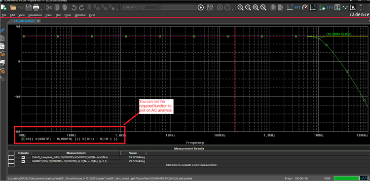
    While performing the AC sweep, you can display the (V(VOUTP)-V(VOUTN)) / (V(IN+)-V(IN-) gain result in decibels (dB). 

    For example, on the waveform viewer you can perform an AC simulation and select Trace --> Add Trace, and define the function you wish to display in the Bode plot.

    For example, the AC signal simulated gain is 28.583dB (or 26.86V/V) with a f(-3dB) corner frequency around 10.2-MHz.

    The following videos below have useful tutorials, providing instructions on how to setup the PSPICE analysis. Here is a few tutorials on PSPICE that may be of interest:

    https://www.ti.com/video/series/explore-pspice--for-ti-design-and-simulation-tool.html

    Also, the tutorial below discusses ADC Input types, and discusses fully-differential ADCs:

    SAR ADC input types

    Although the INA851 is an instrumentation amplifier, it incorporates a fully-differential (FDA) output stage.

    The following TI Precision Labs series, discusses the standard Fully-differential amplifier, and some of the concepts such as output common-mode voltage and differential output voltage, and input differential voltage may be helpful;

    Precision labs series: Fully differential amplifiers

    Thank you and Regards,

    Luis Chioye