This thread has been locked.

If you have a related question, please click the "Ask a related question" button in the top right corner. The newly created question will be automatically linked to this question.

THS4561: Tina simulation results

Part Number: THS4561

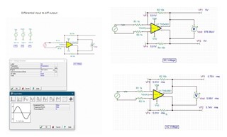
I carried out spice simulation of FDA THS4561 using TINA as per SLOA054 and calculations as per analysis of FDA document

The input signal was ampl 0.5 V, freq 500 K

From calc Vout+ is coming 13 V, Vout- =-3 V, Vout 16 Volt, Vp=Vn= 5/17

Af = infinite

In simulation 

Vout + = 5.75 Vrms

Vout - = 5.74 Vrms

Vout = 5.66 Vrms, 15.8 Vpp

Why vout not equal to vout+ - vout-? And why the values of Vout+ and Vout- not matching with calculated values?

In ac transfer characteristic 

Gain is coming 24 (21 in document) -- how this value is coming?

In transient analysis Vpp is 16 volt for output and Vpp input 1 volt, is this increase due to Rf/Rg = 16?

  • Hi Vinay,

    I was able to look over the document you are referring to. Could you please specify which equations and which portions of the document your results were not lining up with. Could you also attach the TINA file you are running these simulations with. This will be very helpful when working through the concerns you have. 

    Best Regards,

    Ignacio

  • Thanks Ignacio

      Eq 11,13 and 15

  • Hi Vinay,

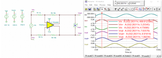
    I was able to get the equations you are referencing to work; I did this by running a transient simulation and by choosing a point in the simulation I was able to use the values at the inputs to apply the formulas to. The image below shows some point in the transient simulation, and I used those values to plug into the equations like I mentioned above. I also attached the schematic. The gain of 24 you see in the ac simulation is 20*log(16V/V), it's the circuits gain converted to dB. As for the transient analysis the gain is due to the choice of Rf and Rg resistors like you mentioned.

    THS4561_OutputSim.TSC

    Best Regards,

    Ignacio

  • Thanks Ignacio

    Can you explain the values in the above picture.

    My query was when I put a probe the values at Vout+ and Vout- were 5.75 Vrms and 5.74 Vrms, in calculation  using  formulas values were 13 and -3. Why?

  • 1. the results I obtained are as in table.

    Vin+=5.01 Vrms in ac nodal voltage, while in graph and calculation it is 0.5 Vpp. Why?

    2. How the levels Vin+ (and Vin-) are +ve peak at 5.26 V and -ve peak at 4.76 V?

    3. Vout+/Vout- = 5.73 Vrms in nodal voltage. How?

    4. Calculation (13 V and -3 V) and Graph (8 Vpp) - Vout+ and Vout- vol are coming different. Why?

  • Hi Vinay,

    The picture I attached is the transient simulation for the circuit and I probed it at one specific point, and it showed me the voltages at those specific nodes. I used these values to confirm the equations are correct that you are referring to. As for the values the ac nodal analysis calculates, it is easier to see the results when considering the amplitude and DC level, which can be shown when you probe the node you are interested in. However, it is easier when using the transient simulation results not the AC nodal analysis. The reason you see 5.26V peak, and not the input signal, it is due to the VOCM offset of 5V which will directly impact the nodes you are referring to. As for the calculations I was successfully able to plug in the values I captured at the VIN+/- nodes and calculate the appropriate Vout+/- values.

    Best Regards,

    Ignacio