This thread has been locked.

If you have a related question, please click the "Ask a related question" button in the top right corner. The newly created question will be automatically linked to this question.

OPA2675: OPA2675: Why the chip get so hot and no output after supply power?

Part Number: OPA2675

Hi ,Experts

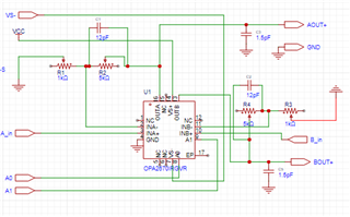
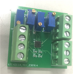
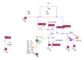
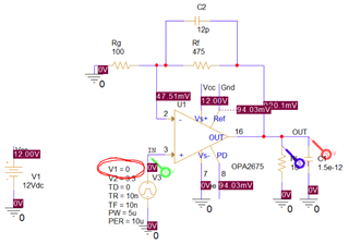
I have design above circuit to test the basic function of OPA2675,

But when I supply ±6V or 12/0V power, it will get hot in seconds and the AOUT+ output nothing!

it's can't find any wiring error or short circuit and I fear the chip will be broken if long time testing.

And the A0 & A1 wiring the GND.

Hope you can reply me as soon as possible~

Thx~ 

  • Hey Joaquin,

    1. Have you made a PCB to test this part or using a breadboard type of setup to test it?

    2. What's the input you are giving at INA+ and INB+ ?

    Regards

    Anant

  • thx your reply~

    I have made a PCB:

    I only used OP-amp A, not OP-amp B, so the INB+ is not for using

    about INA+, the 3.3v PMW wave input

    I want to driver a UV_LED by this circuit

  • I can see two issues in your setup :-

    1. Since channel B is also active, INB+ should not be left floating, doing so can take the output to unknown state and it can even chatter, which can heat up the device

    2.  I don't see any suppy decap in your board. This is a high speed part and without decouping (bypass) capacitor at both supply (VCC and VEE), it might not work properly (see section 9.4.1 and 9.4.2 of the datsheet for more detail).

  • Thank you for reply~

    1. You are right, channel B is active, but the INB input nothing so it is should no output;

    2. OK, I will add the bypass capacitor and test again

    Here are some recent developments:

    1. I replace the 1kΩ load resistor by a 10Ω one, and the max output voltage is only 2.5V which lower than the max voltage according the datasheet. It is should have a way to calculate the  max output power(P=U*I)of OPA2675, but I don't very clearly how to calculate it and why the output (the voltage and current) much lower than parameters on the datasheet?

    2. I build the circuit in "PSpice for TI", and the result show it can output 10V/1A power on 10Ω load resistor, but I have build totally same circuit on breadboard,but the output still lower than the stimulation result.(12V single power supply)

    I am a noob for circuit design, thank your reply and generousBlush

  • Joaquin,

    If you are not using channel B, connect it's input to a know voltage node don't leave it floating.

    Secondly, this is a high speed device, any any parasitic capacitance at inverting input ot the output can make it unstable, so using breadboard (which add too much parasitic) is to test the circuit is not recommended.

    Also the circuit which you share in the last thread, the input common mode condition is getting violated. Please note that this is not a rail to rail input output device. So if you power this device with 12V single supply, your input needs to be within 2.5V to 9.5V. (Please refer to the input and output characteristics of the data sheet's electrical table for mode detail)

    Regards

    Anant

  • Thank you, Anant

    1. I will connect B input to GND according to your useful suggestions.

    2. Just like you said how I can stimulate my circuit if breadboard is not recommended, and I hardly believe the "PSpice for TI" result. Can you give me a circuit schematic which I can test it to drive my UV_LED (voltage=6v, current=0.5A)?

    3. I am not very clearly what your mean. The input is 3.3V which is within 2.5V to 9.5V. (I guess you mean the output voltage, but why it can higher than 9.5V in "PSpice for TI"?  )

    Wish you have a lovely day~

  • Joaquin,

    There is an EVM available which you can get from TI.com to test yor circuit (link below)

          https://www.ti.com/tool/DEM-OPA-RGV-EVM

    In your schematic (snippet below) the input swings from 0V to 3.3V, so for the time period in which it is 0V, it will violate the Input common mode and output operating range. 

    Regards

    Anant