This thread has been locked.

If you have a related question, please click the "Ask a related question" button in the top right corner. The newly created question will be automatically linked to this question.

LM393B: LM393B vs. LM393M

Part Number: LM393B
Other Parts Discussed in Thread: LM393, LM393LV

Hello all, I am currently having issues with the LM393BIDR, we have been using the LM393M. We use it to make a saw tooth generator, but the LM393BIDR is not performing as a drop in replacement.

We have been using the LM393M for over 10 years or so, purchased the LM393BIDR and we are not having a sawtooth output, it is just 5V high. 
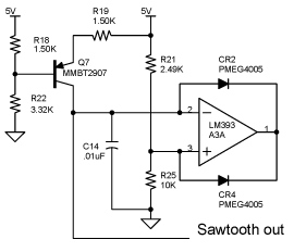
Attacjh is schematic. Any ideas?

Thank you. 

  • Hello Gary,

    It would be helpful to see a scope photo of the waveforms...but I think I can see what is happening.

    Please see the LM393 family appnote:

    Application Design Guidelines for LM339, LM393, TL331 Family Comparators

    The threshold is set to 4V by R21/R25, which places it way outside of the specified input voltage range (Vcc-2V).

    The difference in the behavior of the new and old die occurs when BOTH inputs are outside the specified input range (>4V). The "classic" die output flopped low, and the "new" die output flops high under this condition.

    For the last 10 years, you relied on the fact that the output would "flop" low when the input range was violated and you never noticed it. The "new" die "flops" high, and jams-up the works. It gets "stuck".

    The R21/R25 threshold needs be be set to under 3V to avoid the inversion. A quick fix is to try using a LM393LV - which has a R-R input.

  • Hello Paul, 

    thank you for the reply!

    I will try setting R21/R25 to 2.5V and see if the sawtooth waveform comes back with a peak voltage of 2.5V. 

    Thanks again, 

    Gary

  • I have changed the R21/R25 to 2.5V, but no I still do not get the sawtooth waveform. But as of now we will just rework our products with a nonB version LM393. 

  • HI Gary,

    Hmmm...Can we see scope photos of a working circuit?

    Have you tried the LM393LV? It's Rail to Rail inputs eliminate the reversal issue.

    Due to the PCN's, you will eventually get a "B" device...so you really want to keep the circuit from being dependent on a particular device.

  • Hi Paul, 

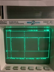
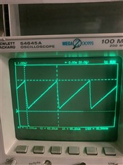
    here are the scop captures at the LM393 pins:

    PINS 1 and 3:


    PIN 2:

    Thank you, 

    Gary

  • Hi Gary,

    It looks like the graticule division markings on the scope screen are turned off. Kinda hard to see the actual voltages.

    I assume this is the "working" version. What are the voltages on pins 2 and 3 when it is "stuck"?

  • Hi Gary,

    Thought: What happens if you temporarily ground the output pin 1 on the "B" device? Does it start working?

  • Hi Paul,

    When grounding pin 1 momentarily, the output pin 2 goes low and immediately goes high when the ground is released. I am using the R21/R25 values that is on the attached schematic.

    When changing R21/R25 to 2.5V, the output pin 2 just remains low when momentarily grounding pin 1. 

    Thank you, 

    Gary

  • Hi Gary,

    I tinkered with your circuit in simulation. It's what I suspected...

    Your original "10 year" circuit set the positive pin to 4V through R21/R25 with the 10k resistor. 4V violates the VCC-2V rule.

    The capacitor also charges up to above 4V. This also violates the VCC-2 rule.

    For the "old" device, when BOTH inputs are above the limit (>4V), the output fails low - which is what you actually want.

    You have been relying on this little "feature" for years.... Technically the output should have been indeterminate and should not have worked. If you were ever having problems at cold temperatures - that's why...

    The new "B" device output goes high when BOTH inputs are violated - and this is why it gets stuck high.

    Changing R25 to 2.5K moves the positive input down to 2.5V - well within the limit. As well as the capacitor upper charge limit.

    The disadvantage is that this limits the amplitude of the triangle wave. I'm still puzzled as to why the "B" still did not work. That's why I asked you to short the output to force it low and hopefully get things started. Take a close look at the start-up (the first few cycles).

    But what I would actually recommend is that you switch to a Rail-to-rail input device, such as the LM393LV to eliminate the inpurt headroom issue. Then you can go back to your 10K and get the larger 4V swing (maybe a bit more!).

  • Hi Gary,

    Just to confirm that this is with the "B" device? Or the "old" device?

    Grounding pin 1 (comparator output) should drag pin 2 down through the CR2 diode and discharge the cap.

    When released, the cap should start charging up (ramping on pin 2).

    Do both pin 2 and 3 go low when the pin 1 output is shorted? Pin 3 should immediately bounce back to 2.5V.

    What are the actual voltages measured (with a DMM) on pins 1, 2 and 3? when stuck low?

  • Hello Paul, 

    with the stuck version with a R21/R25 at 2.5V, Pin 2 is 185mV and Pin 3 is 176mV.

    Thank you, 

    Gary

  • Hi Gary,

    This is strange...

    Please confirm:

    The "old" LM393 works on both the 2.5k and 10k circuits?

    The "B" version does NOT work on both the 2.5k and 10k circuits?

    Do you have access to a 4 channel scope? Even a cheap, slow one? It would be good to see Pins 8, 2, 3, and 1 together on one screen.

    Or, using your 2 channel, can you look at pin 1, 2, and 3 individually while triggering of the supply. Keep the positions and sensitivity the same (just move the probe). And turn on the graticle...(Display->Grid->Full)

    Trigger off the supply (pin 8) with the trigger level set to 0.3V and set the triggger to single or turn off "auto" trigger.

    I'm curious about the start-up behavior.