This thread has been locked.

If you have a related question, please click the "Ask a related question" button in the top right corner. The newly created question will be automatically linked to this question.

LOG114: LOG114EVM - Can we somehow modify it to accept 0 - (-)100uA input.

Part Number: LOG114
Other Parts Discussed in Thread: , OPA365, OPA192

Is it possible to modify the LOG114EVM for negative input current.  Our PMT produces negative current and we bought LOG114EVM's for processing but realized after we need negative current input supported, can we modify via Vref or Vbias changes to Neg voltages or other ideas?   We desire not to add on deadbug current inversion opcamp circuit.

Desired 
0 to -100uA input
0-4V output (or some reasonable Vout range 3V or larger, larger the better)

  • Hi Shawn,

    The voltage references and/or the positive/negative bias voltages may allow you to create a positive or negative offset current, that can be used to substract to your PMT signal.  However, not sure if this will provide the logarithmic output you expect.  Since you require a logarithmic output as a function of the ~100pA  to 100μA PMT negative input current, you will likely need to implement a current inverter.  The current inverter circuits I am familiar with, involve op-amps.

    The LOG114 datasheet has a couple of suggestions for current inverters on Figure 7 involving one op-amp and two BJTs, and Figure 8 involving a dual amplifier.

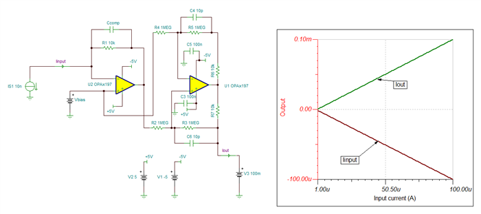
    Another example of a precision current inverter using a dual amplifier is below, the first stage is a transimpedance amplifier, followed by a Howland Current source stage:

    Is this circuit for a unipolar +5V supply or bipolar ±5V supplies? 

    What is the stray capacitance at the input current inverter circuit / output of PMT sensor?

    We do offer a couple of evaluation boards that may allow you to wire or setup op-amps circuits on different configurations, that could make the setup easier.  For example:

    DIYAMP-EVM — Universal do-it-yourself (DIY) amplifier circuit evaluation module

    Kindly let me know your supply requirements, and I can also look into suggesting a detailed LOG114 circuit accordingly.

    Thank you and Regards,

    Luis 

  • thanks Luis, Currently we only supply +5V, but we certainly could supply + and - supplies if needed.  Ideally a modification to the LOG114 a current invertor EVM if that might exist.

  • HI Shawn,

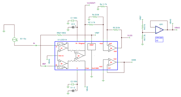
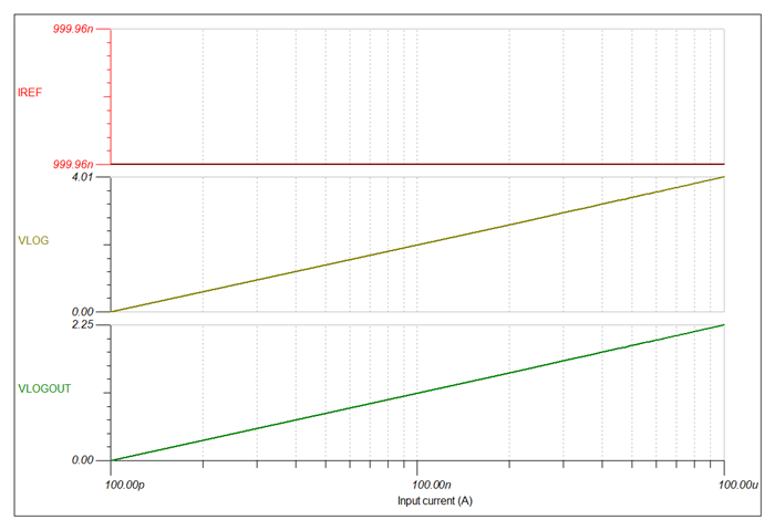
    Connecting the LOG114 in the circuit below with bipolar ±5V provides a 0-4V output for a 100pA to 100uA input.

    VBIAS is set to 1.5V using U2 (OPA365) on the LOG114EVM/

    IREF is set to 1uA using the RREF=1MΩ.  OP AMP A4 is set as a difference amplifier on a gain of 1.778V as shown below.

    The LOG114EVM will require some re-wiring as this is not the standard default configuration on the evaluation board.

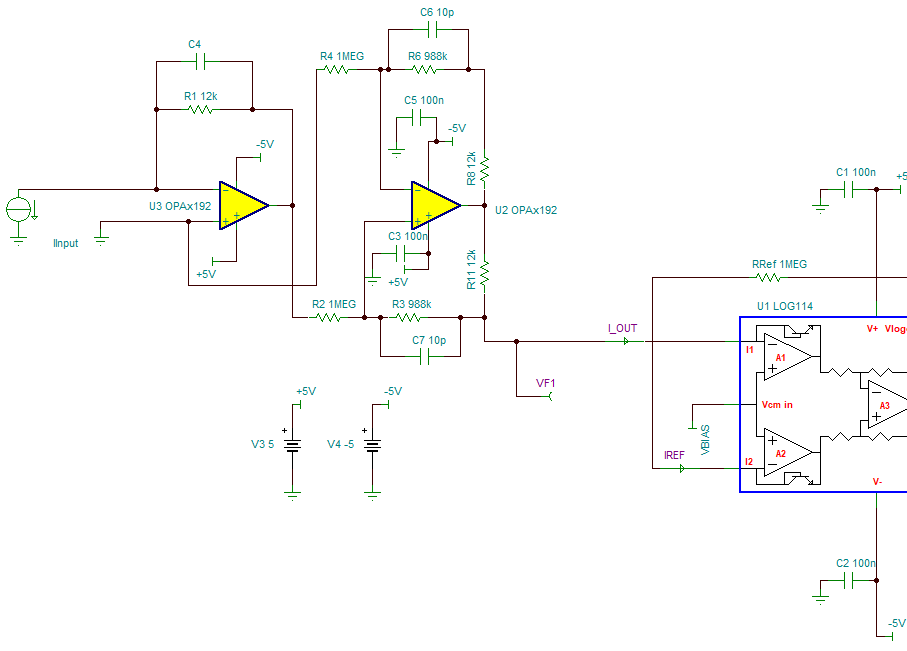
    For the current inversion circuit, the below is one possibility using the OPA192 supporting bipolar ±5V supplies.  I have not found a standard evaluation board that provides this circuit, but I believe it is possible a couple of the DIY modules.  If I find an existing eval board that easily allows to implement this circuit, I will update.

    Thank you and Regards,

    Luis

    DIYAMP-EVM — Universal do-it-yourself (DIY) amplifier circuit evaluation module

  • Hi Shawn,

    The closest PCB evaluation board I found as far to implement the current inverter circuit, is the Dual-channel universal do-it-yourself (DIY) amplifier circuit evaluation module:

    DUAL-DIYAMP-EVM

    Dual-channel universal do-it-yourself (DIY) amplifier circuit evaluation module

    Thank you and Regards,

    Luis