This thread has been locked.

If you have a related question, please click the "Ask a related question" button in the top right corner. The newly created question will be automatically linked to this question.

INA238: Schematic review for SMC

Part Number: INA238

Hi Team,

This is urgent but can you please help us review the attached schematic ?

INA238_FOR TI REVIEW_09182023.pdf

SMC also have the following questions:

 "

1)Does TI have i2c dongle/software to read current/power for this part? If so I’ll want to reserve a test header

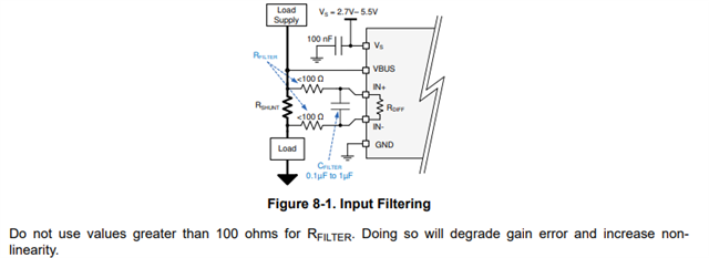
2)can you suggest a value for the Rfilter and cap based on my application?  


Application:

Input: 12v or 54v

Imax: 60 A for 12v or 15A for 54v  (~700W)


Note: SDA and SCL has 4.7k ohms pull-up resistors in another page 

Note: Rsense is 0.5 m-ohm power rating 3W part"

Please get back to me ASAP. Thanks.

Regards,

Anuj

  • Adding one more request from SMC:

    "

    What’s the suggested trace width for the sense paths (In- and In+) for this application?"

    Regards,

    Anuj

  • Hi Anuj, 

    My only question about your schematic has to do with the shunt resistors. You seem to have 2 0.5mOhm resistors in parallel, which would yield a smaller total resistance and you mentioned that your shunt was 0.5mOhm. Was this intentional? Having 2 resistors in parallel could introduce other issues as well depending on the values. 

    As for the other questions:

    1) Yes. TI offers an EVM along with the EVM software for you to test the IC and visualize current/power along with other metrics. It is quite easy to use and proves to be very useful: 

    https://www.ti.com/tool/INA228_237_238EVM

    2) According to our datasheet, we recommend a filter resistor of <100ohm and a capacitor of 0.1uF to 1uF. 

    3) For the sense line, it shouldn't matter much as there is very little current flowing into the IN+ and IN- pins. Other information on how to choose a shunt resistor and good layout practices can be found here: www.ti.com/.../6076324596001

    Best,

    Mohamed 

  • Hi Mohamed,

    This is what I received from our SMC after I shared your feedback with them:

    "If you look closely you can see one of the sense resistors has a X on it, that’s our secret code to reserve the space as I am not planning to populate it at the moment.

    I reserve a space there in case the power consumption is larger than expected , or if the fan modules require larger power in the future.


    For 2) , the datasheet only mentions 10-ohm to protect up to 40v max short circuit scenario, for my case of 54v, is that enough?

    I’ll play around the tools and get back to you if I have further questions."

    Regards,

    Anuj

  • HI Anuj, 

    The wording is a bit confusing on the datasheet. I will attempt to contact the Systems engineer who wrote this and get back to you Monday. 

    Best,

    Mohamed 

  • Thanks Mohamed. I'll wait for your response.

    Regards,

    Anuj

  • Hi Anuj,

    There are no circumstances where a differential voltage of over 40V could be applied without damaging our device. However it is worth noting that this is differential voltage between the IN+ and IN- pins, not necessarily the common mode voltage. 

    Best,

    Mohamed