Because of the holidays, TI E2E™ design support forum responses will be delayed from Dec. 25 through Jan. 2. Thank you for your patience.

This thread has been locked.

If you have a related question, please click the "Ask a related question" button in the top right corner. The newly created question will be automatically linked to this question.

OPA356: Decoupling capacitor

Part Number: OPA356

Hello all,

The OPA356 datasheet says: "A 10µF ceramic bypass capacitor is the minimum recommended value; adding a 1µF or larger tantalum capacitor in parallel can be beneficial when driving a low-resistance load. Providing adequate bypass capacitance is essential to achieving very low harmonic and intermodulation distortion."

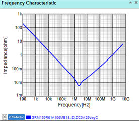
According to the datasheet, I need to place a minimum 10µF ceramic bypass capacitor in order for the Op Amp to function well. However, if we see the graph impedance versus frequency, we will notice that most of the 10µF capacitors will act as an inductor for high-frequencies. Below are some examples from muRata design tool.
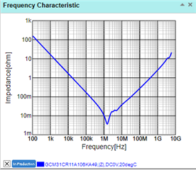
So, for high-frequencies, should I use a bypass capacitor that works as a capacitor in my frequency range? Or should I follow the datasheet and use a minimum 10µF ceramic bypass capacitor?

Thank you in advance.

Best regards,

João Rego

  • A general recommendation is to have 0.1 µF near the device, and 10 µF at the power supply, shared by all devices.

    Decoupling capacitors protect the power supply rails against quick changes in the load current. If the OPA356 does drive a large load, and if you have high-frequency signals, then it might be necessary to add decoupling for these specific frequencies. (But note that the inductance of the pins and bond wires limits what you can do with an external capacitor.) For extreme applications, it might be necessary to experiment with the actual board.