This thread has been locked.

If you have a related question, please click the "Ask a related question" button in the top right corner. The newly created question will be automatically linked to this question.

INA219: INA219 current calculations

Part Number: INA219


Hello experts,

I'm attempting to read the current from an INA219 device. I've successfully read the bus voltage, indicating that the I2C driver is working correctly. However, when I read the current, I receive values that are approximately 2.2 times higher than expected (I verified this by comparing with a Fluke measurement). The current I'm working with is about 400-500 mA according to Fluke measurements, so this discrepancy is significant.

Here are the default values I've set:

#define INA219_SHUNT_RESISTOR_Ohm 0.004f
#define INA219_CURRENT_LSB_A 0.0004f
#define INA219_CALIB_VALUE (((uint16_t)(0.04096f / (INA219_CURRENT_LSB_mA * INA219_SHUNT_RESISTOR_Ohm))) << 1)
#define INA219_POWER_LSB_W (INA219_CURRENT_LSB_A * 20.0f)

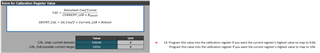
The register values are:
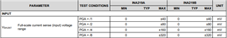
0x00 Configuration 0x0443 Gain = 1; Range = 40mV, BADC = 1 (bus oversampling), SADC = 1 (shunt oversampling), Shunt and bus, triggered
0x05 Calibration 0xC800

ina219.bus_voltage = (float)(bus_voltage_raw >> 3) * 4.0;               // mV
ina219.shunt_voltage = (float)((int16_t)shunt_voltage_raw) / 100.0;     // mV
ina219.current = (float)current_raw * INA219_CURRENT_LSB_A * 1000.0;    // mA
ina219.power = (float)power_raw * INA219_POWER_LSB_W * 1000.0;          // mW

Could you please kindly help me identify the mistake? I've checked myself multiple times and haven't been able to find it.

Thank you in advance,
Genadi.

  • Hi,

    Are all your current values around 2.2x times the current reading you are expecting?

    If this is the case, then it is likely that it's a simple error in the calibration register value, and the digital code in the register doesn't map to the appropriate value you are expecting. 

    We have a power monitor tool that will give you the value to write to the configuration register depending on your device and parameters.

    It can be downloaded here: SBOR021 Calculation tool | TI.com

    This is an example of what would need to be written to the calibration register depending on what current you want to map to the highest digital value in the register. 

    What are approximately the lowest and largest current values you will be measuring?

    Is 400-500mA the range that will be covered?

    If this is the case, you might want to consider going with a larger shunt resistance value.

    With your highest current of 500mA you are only developing 2mV across your 4mΩ shunt, which is only a fraction of the ±40mV range available from your configuration. 

    This translates to less accuracy in measurements, which could be another reason the values aren't what you expect.

    Best Regards,

    Angel

  • Thank you, Angle, for your thorough response.

    The current I'm measuring can range anywhere from 20 mA to 2000 mA. I don't necessarily need very precise measurements, but a 2.2 times difference is quite significant. My main concern is ensuring that the system functions correctly without any unexpected issues.

    I appreciate the tool you provided earlier. However, when I input my parameters, the results were a bit unclear. It suggested setting the current LSB to 0.000061035 and the calibration register value to 167772. Yet, based on the datasheet, the calibration value is 15 bits long, so this recommendation exceeds the allowed range. That's why I've chosen to set the current LSB to 0.0004 A.

    I've taken steps to validate the value written to the calibration register by reading it and using an oscilloscope. This suggests that the problem may lie elsewhere in the system.

    Could you please confirm whether the equations I'm using are correct?

  • Hi Genadi, 

    I will consult with the team for possible suggestions to solve this issue and to verify what should be written to the configuration and calibration registers based on your setup. 

    In the meantime, can you provide us with as many details as possible from your setup? This will help us determine if something else could be the issue or help us give suggestions on what to write to your configuration registers.

    Is your Current reading always 2.2 times larger than what you expect, or do the results vary significantly?

    What exactly are you reading from the current register, and what were you expecting to see instead (Output codes in decimal/Hex/binary)?

    What about the shunt voltage register readings?

    What is your VS power supply, Bus Voltage, etc? 

    Can you provide us with a schematic?

    Best Regards,

    Angel

  • Hi Angle,

    Here is the shunt resistor in the circuit:

    and here is the ina219 itself:

    Here is the table of the raw readings I get from I2C and the current and shunt voltage I get after a conversion:

    current_raw currnet_mA shunt_voltage_raw shunt_voltage_mV FLUKE_mA
    0x41A 420 0x54 0.84 173.5
    0x3DC 395.199982 0x4F 0.79 173.5
    0x41A 420 0x54 0.84 173.5
    0x3B6 380 0x4C 0.76 173.5
    0x41A 420 0x54 0.84 173.5
    0x40E 415.199982 0x53 0.83 173.5
    0x40E 415.199982 0x53 0.83 173.5
    0x41A 420 0x54 0.84 173.5
    0x3B6 380 0x4C 0.76 173.5
    0x41A 420 0x54 0.84 173.5
    0x3B6 380 0x4C 0.76 173.5
    0x41A 420 0x54 0.84 173.5
    0x41A 420 0x54 0.84 173.5
    0x41A 420 0x54 0.84 173.5
    0x41A 420 0x54 0.84 173.5
    0x3AA 375.200012 0x4B 0.75 173.5
    0x41A 420 0x54 0.84 173.5
    0x3B6 380 0x4C 0.76 173.5
    0xFFFFFF77 -54.799999 0xFFFFFFF5 -0.11 -61.3
    0xFFFFFF77 -54.799999 0xFFFFFFF5 -0.11 -61.3
    0xFFFFFF77 -54.799999 0xFFFFFFF5 -0.11 -61.3
    0xFFFFFF77 -54.799999 0xFFFFFFF5 -0.11 -61.3
    0xFFFFFF77 -54.799999 0xFFFFFFF5 -0.11 -61.3
    0xFFFFFF77 -54.799999 0xFFFFFFF5 -0.11 -61.3
    0xFFFFFF77 -54.799999 0xFFFFFFF5 -0.11 -61.3
    0xFFFFFF83 -49.999996 0xFFFFFFF6 -0.1 -61.3
    0xFFFFFF77 -54.799999 0xFFFFFFF5 -0.11 -61.3
    0xFFFFFF77 -54.799999 0xFFFFFFF5 -0.11 -61.3
    0xFFFFFF77 -54.799999 0xFFFFFFF5 -0.11 -61.3
    0xFFFFFF77 -54.799999 0xFFFFFFF5 -0.11 -61.3
    0xFFFFFF83 -49.999996 0xFFFFFFF6 -0.1 -61.3
    0xFFFFFF77 -54.799999 0xFFFFFFF5 -0.11 -61.3
    0xFFFFFF83 -49.999996 0xFFFFFFF6 -0.1 -61.3
    0xFFFFFF83 -49.999996 0xFFFFFFF6 -0.1 -61.3
    0xFFFFFF83 -49.999996 0xFFFFFFF6 -0.1 -61.3

    At this stage the difference between the INA219 values vs FLUKE values is about x0.41 for positive values and x1.15 for negative.

    I previously mentioned that when I take the voltage and divide it by the resistance (0.004 Ohms), I get a current value that's twice as high. I decided to make a further adjustment by modifying the calibration register equation and removing the shift operation:
    #define INA219_CALIB_VALUE ((uint16_t)(0.04096f / (INA219_CURRENT_LSB_mA * INA219_SHUNT_RESISTOR_Ohm)))
    instead of:
    #define INA219_CALIB_VALUE (((uint16_t)(0.04096f / (INA219_CURRENT_LSB_mA * INA219_SHUNT_RESISTOR_Ohm))) << 1)
    As a result, I found that the current value I obtain now aligns with the V/R=I equation. I also checked that I am not trying to shift the calibration value twice in the code.
    Here are some samples for example:
    current_raw currnet_mA shunt_voltage_raw shunt_voltage_mV FLUKE_mA
    0x1DB 190 0x4C 0.76 173.3
    0x20D 210 0x54 0.84 173.3
    0x1D5 187.600006 0x4B 0.75 173.3
    0x20D 210 0x54 0.84 173.3
    0x20D 210 0x54 0.84 173.3
    0x207 207.599991 0x53 0.83 173.3
    0x20D 210 0x54 0.84 173.3
    0x1D5 187.600006 0x4B 0.75 173.3
    0x20D 210 0x54 0.84 173.3
    0x1E1 192.399994 0x4D 0.77 173.3
    0x20D 210 0x54 0.84 173.3
    0x20D 210 0x54 0.84 173.3
    0x1DB 190 0x4C 0.76 173.3
    0x20D 210 0x54 0.84 173.3
    0x1D5 187.600006 0x4B 0.75 173.3
    0x20D 210 0x54 0.84 173.3
    0x20D 210 0x54 0.84 173.3
    0x20D 210 0x54 0.84 173.3
    0x20D 210 0x54 0.84 173.3
    0x1DB 190 0x4C 0.76 173.3
    0x20D 210 0x54 0.84 173.3
    0x1D5 187.600006 0x4B 0.75 173.3
    0x20D 210 0x54 0.84 173.3
    0x20D 210 0x54 0.84 173.3
    0x1DB 190 0x4C 0.76 173.3
    0x20D 210 0x54 0.84 173.3
    0x1D5 187.600006 0x4B 0.75 173.3
    0x207 207.599991 0x53 0.83 173.3
    0xFFFFFFBB -27.6 0xFFFFFFF5 -0.11 -59
    0xFFFFFFBB -27.6 0xFFFFFFF5 -0.11 -59
    0xFFFFFFBB -27.6 0xFFFFFFF5 -0.11 -59
    0xFFFFFFBB -27.6 0xFFFFFFF5 -0.11 -59
    0xFFFFFFB5 -30 0xFFFFFFF4 -0.12 -59
    0xFFFFFFBB -27.6 0xFFFFFFF5 -0.11 -59
    0xFFFFFFBB -27.6 0xFFFFFFF5 -0.11 -59
    0xFFFFFFB5 -30 0xFFFFFFF4 -0.12 -59
    0xFFFFFFBB -27.6 0xFFFFFFF5 -0.11 -59
    0xFFFFFFB5 -30 0xFFFFFFF4 -0.12 -59
    0xFFFFFFC2 -24.799999 0xFFFFFFF6 -0.1 -59
    0xFFFFFFBB -27.6 0xFFFFFFF5 -0.11 -59
    0xFFFFFFBB -27.6 0xFFFFFFF5 -0.11 -59
    0xFFFFFFBB -27.6 0xFFFFFFF5 -0.11 -59
    0xFFFFFFBB -27.6 0xFFFFFFF5 -0.11 -59
    0xFFFFFFBB -27.6 0xFFFFFFF5 -0.11 -59
    0xFFFFFFBB -27.6 0xFFFFFFF5 -0.11 -59
    0xFFFFFFBB -27.6 0xFFFFFFF5 -0.11 -59
    0xFFFFFFBB -27.6 0xFFFFFFF5 -0.11 -59
    0xFFFFFFBB -27.6 0xFFFFFFF5 -0.11 -59

    At this stage the difference between the INA219 values vs FLUKE values is about x1.15 for positive values and x2 for negative.

    As a power source I use USB and li-ion battery 3.6V, 2350 mAh, 8.46 Wh.

    Please let me know if there is any other pertinent information I can provide to assist you further.

    Best regards, Genadi.

  • Here is another example with oscilloscope:

    This is a write-read current register operation. 

    The value I read from the sensor (by software) is 0x019d which is identical to what we can see on the picture (if the first byte in the sequence is MSB).

    When I translate the current_raw value from the register to current value (ina219.current = (float)current_raw * INA219_CURRENT_LSB_A * 1000.0) in mA I get 165.2 mA, when the FLUKE shows me 45.6 mA.

    Do you have any ideas?

    Best regards, Genadi.

  • And here is the write operation to the config register:

    This value represents 0xC800, exactly as expected.

  • Hi Genadi,

    Your digital communications are clearly working, as you wouldn't be able to read back any information from the registers otherwise.

    #define INA219_CALIB_VALUE ((uint16_t)(0.04096f / (INA219_CURRENT_LSB_mA * INA219_SHUNT_RESISTOR_Ohm)))
    instead of:
    #define INA219_CALIB_VALUE (((uint16_t)(0.04096f / (INA219_CURRENT_LSB_mA * INA219_SHUNT_RESISTOR_Ohm))) << 1)

    The first way without shifting is the way to do it. The current value should align with the Vshunt = I * Rshunt equation. After making the change you can see from your second table of results how doing it this way the values align with the equation and are also much closer to you FLUKE measurement values.

    There seems to be two issues at hand, there values change slightly from one measurement to the next, and there is an offset of around 30mA. 

    From the average there is an offset of around 30mA for both the positive and negative current measurements. Average value for positive currents from your second table = 202.34mA, (202.34mA - 30mA = 172.34mA much closer to your FLUKE value of 173.3mA). Average value for negative currents = -27.82mA, (-27.82mA - 30mA = -57.82mA much closer to your FLUKE measurement of -59mA). Around 25mA of offset is caused by Vos. Vos is the dominant source of error for the lower current measurements in your range. Ios = Vos/Rshunt = 100uV/4mΩ = 25mA. The other 5mA is caused by a difference in bias current from the in+ and in- pins.

    These numbers can be found in the data sheet. 

    I would suggest replacing R31 and R38 with 0Ω resistors as that might help removing additional offset caused input bias current differences between in+ and in-.

    The variation from one current measurement to another are likely due to noise. Your measurements are sensitive to noise because your shunt resistor is quite small, and the Voltage signal developed across it is small as a result. At you Max current of 2A, the Vshunt max is only 8mV, and you have 40mV available from your configuration. 

    I would suggest if possible to increase the shunt resistor to increase your Vshunt signal, this would allow for much more accuracy. 

    Best Regards,

    Angel