This thread has been locked.

If you have a related question, please click the "Ask a related question" button in the top right corner. The newly created question will be automatically linked to this question.

OPA325: What are input impedance of OPAx325 and OPAx377?

Part Number: OPA325
Other Parts Discussed in Thread: OPA377,

Dear Friend

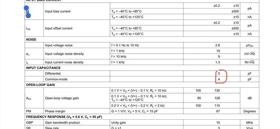
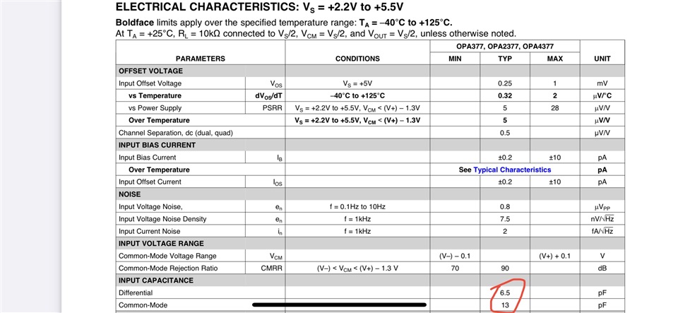
I do not find input impedance data of OPAx325 and OPAx377 from their datasheet.  while I can find this data from OPAx388 datasheet. 

why not providing this important data? any particular reason? Does this mean that I should have particular consideration when selecting these amplifiers?

Thanks for answering such an unfavorable question. 

Regards

Tony

  • Tony,

    The common-mode and differential input resistance of OPA325 and OPA377 are extremely high - around 10^13 (10Tohm) while common-mode and differential input capacitance is given in their respective datasheets - see below.


  • For CMOS devices, the input bias current is mostly leakage through the ESD protection structures. So it is extremely small, and in most cases, a single impedance value would not be able to accurately describe the behaviour. In general, the input bias current specifications are sufficient to choose an amplifier.

  • Hi Marek Lis

    Thank you for your reply.  I saw the input bias current/capacitance data.

    Do you mean users can estimate input impedance from the input bias current/capacitance? if yes, how? Are there any formulas helping such estimation?

    and why TI do provide input impedance data for certain CMOS amplifier chips that are very similar to those without input impedance data (if input bias current could directly reflect/indicate the input impedance)?

    Thanks

    Tony


  • Hi Clemens

    Thank you for your explanation.

    From the figure you provided, the input bias current will increase rapidly when Vcom >2V,  does that mean input impedance also has the same characteristic(inversely)?  What is the actual relationship between input bias current and input impedance?

    My previous impression was that: input bias current is a result of input structure and is fixed, while input impedance is a result of total input parasitic and resistance, so is input voltage dependent/related,  and total input current will be the sum of the two....that is why I keep thinking both input bias current and input impedance datas are very important.  

    Please enlighten me so I will not be confused when selecting TI CMOS amplifiers, since some of them with input impedance data and some of them without.

    Thanks

    Tony

  • The specified input bias current is the total input current.

    For CMOS amplifiers, there usually is no simple voltage/current relationship, so specifiying an impedance would not be useful.

  • The average Rin_cm may be calculated from the IB vs Vcm graph (see below) to be around 300Gohm but its instantaneous value changes and may be shown to be a tangent slope at any give Vcm point. This is the reason why no Rin_cm is given in the datasheet but may be derived from graph below for specific condition.

    Because OPA325 has an internal charge pump (see below), which causes IB to increase significantly close to positive rail due to impact ionization, the effective Rin_cm is the lowest close to positive rail but remains in Gohm range.

  • Hi Marek Lis

    Thank you for the explanation.

    So it seems like I can always assume that those parts without impedance or not given will have higher impedance than those with impedance data. right?

    Thanks for your support.

    Tony

  • I would say you should look for IB vs Vcm graph to confirm. The input impedance of CMOS and JFET input op amps is very high while bipolar transistor input op amps have much lower input impedance.