This thread has been locked.

If you have a related question, please click the "Ask a related question" button in the top right corner. The newly created question will be automatically linked to this question.

USB2ANY: USB2ANY Interface Adapter

Part Number: USB2ANY
Other Parts Discussed in Thread: MSP430FR5994, , UNIFLASH

Hi team,

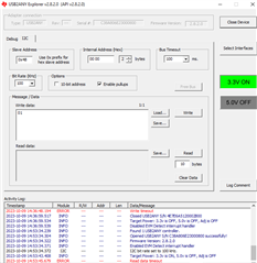
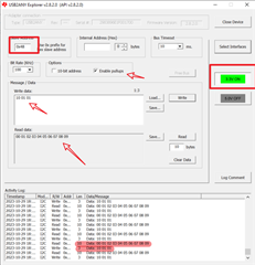
I am using USB2ANY interface adapter to read the registers of the MSP430FR5994 MCU using I2C interface. However, I could not able to read the registers. Attached is the snapshot for your reference. Could you please help me in fixing this issue?

  • I see that the USB2ANY adapter is communicating with the USB2ANY explorer program, so I think this part of the chain is probably working. You may want to probe the I2C lines with an oscilloscope and confirm that the USB2ANY is sending the correct signals on the expected wires - the I2C lines and the GND line all need to be connected for communication to work.

    If you can probe the bus and show a transaction that you are confident should be working, then I expect the issue is with the MSP430FR5994 configuration - not my area of expertise, but I can have someone from the MSP430 support team take a look.

  • Thanks, Payne for your reply. Could you please add an MSP430FR5994 expertise and help us in resolving this issue? 

    We are using the MSP‑EXP430FR5994 EVK. I have converted the msp430fr59xx_eusci_i2c_standard_slave.c into .out using CCS tool and programmed the EVK using Uniflash software. Now I am trying to read the registers of MSP430FR5994 using USB2ANY adapter, but it is not working. 

    So, could you please help me in debugging this issue?

  • I passed this along to MSP430 - someone should follow up with you shortly.

  • Hi Swaroop,

    The code you used include some application level protocol, you can try use this code for your test firstly:

    https://dev.ti.com/tirex/explore/node?node=A__AIxMqO6Wsyyga7bdYuWczg__msp430ware__IOGqZri__LATEST

    Thanks!

    Best Regards

    Johnson

  • Hi Johnson,

    I tried this code, but it didnot work.

  • Hi Swaroop,

    Have you tried reset MCU, then run communication via USB2ANY?

    Those examlpe code should test pass in our side.

    And hardware connection is correct?

    Do you have some Logic Analysis to capture some waveform here?

    I can try do some test in my side if you still can't communication successful.

    Thanks!

    Best Regards

    Johnson

  • Hi Johnson,

    I have verified that USB2ANY adapter is providing the clock with the required frequency. I have attached the snapshot for your reference.

    However, after connecting the USB2ANY EVK to the MSP430FR5994 EVK using jumpers ( SCL, SDA and GND) clock is not at all coming. Clock is being held low by the MSP430 EVK...

    If i probe the clock and data signals of MSP430 without connecting to the USB2ANY adapter, it is showing always high (3V3) as expected.

    So could please help me how to proceed further?

    Regards,

    Swaroop P S

  • Hi Swaroop.

    It looks like the I2C clock signal is correct if disconnect MSP430, but if connect MSP430, the voltage will always keep low.

    I tink maybe need to check hardware connect, maybe there are some error.

    And if you can share the hardware connection you used, I can help to check and maybe do some test in my side.

    Thanks!

    Best Regards

    Johnson

  • Hi Johnson,

    Please find the hardware connection below.

    * J4.1 of USB2ANY to P7.0 of MSP430.

    J4.2 of USB2ANY to P7.1 of MSP430 

    * J4.5 of USB2ANY to GND pin of MSP430...

    Please let me know if you need any other details.

    Regards,

    Swaroop P S

  • Hi Swaroop,

    I looked this example and did some test in my side, the default example only have read funciton, if you send some data from USB2ANY, you will encounter some issue(maybe timeout).

    I added some code(enable RX interrupt and read RXBUF data), now you can try this code, this should be able to read and write I2C data:

    #include <msp430.h>
    
    volatile unsigned char TXData;
    volatile unsigned char RXData;
    
    int main(void)
    {
        WDTCTL = WDTPW | WDTHOLD;
    
        // Configure GPIO
        P7SEL0 |= BIT0 | BIT1;
        P7SEL1 &= ~(BIT0 | BIT1);
    
        // Disable the GPIO power-on default high-impedance mode to activate
        // previously configured port settings
        PM5CTL0 &= ~LOCKLPM5;
    
        // Configure USCI_B2 for I2C mode
        UCB2CTLW0 = UCSWRST;                    // Software reset enabled
        UCB2CTLW0 |= UCMODE_3 | UCSYNC;         // I2C mode, sync mode
        UCB2I2COA0 = 0x48 | UCOAEN;             // own address is 0x48 + enable
        UCB2CTLW0 &= ~UCSWRST;                  // clear reset register
        UCB2IE |= UCRXIE0 | UCTXIE0 | UCSTPIE;            // transmit,stop interrupt enable
    
        __bis_SR_register(LPM0_bits | GIE);     // Enter LPM0 w/ interrupts
        __no_operation();
    }
    
    #if defined(__TI_COMPILER_VERSION__) || defined(__IAR_SYSTEMS_ICC__)
    #pragma vector = EUSCI_B2_VECTOR
    __interrupt void USCI_B2_ISR(void)
    #elif defined(__GNUC__)
    void __attribute__ ((interrupt(EUSCI_B2_VECTOR))) USCI_B2_ISR (void)
    #else
    #error Compiler not supported!
    #endif
    {
        switch(__even_in_range(UCB2IV, USCI_I2C_UCBIT9IFG))
        {
            case USCI_NONE:          break;     // Vector 0: No interrupts
            case USCI_I2C_UCALIFG:   break;     // Vector 2: ALIFG
            case USCI_I2C_UCNACKIFG: break;     // Vector 4: NACKIFG
            case USCI_I2C_UCSTTIFG:  break;     // Vector 6: STTIFG
            case USCI_I2C_UCSTPIFG:             // Vector 8: STPIFG
                TXData = 0;
                UCB2IFG &= ~UCSTPIFG;           // Clear stop condition int flag
                break;
            case USCI_I2C_UCRXIFG3:  break;     // Vector 10: RXIFG3
            case USCI_I2C_UCTXIFG3:  break;     // Vector 12: TXIFG3
            case USCI_I2C_UCRXIFG2:  break;     // Vector 14: RXIFG2
            case USCI_I2C_UCTXIFG2:  break;     // Vector 16: TXIFG2
            case USCI_I2C_UCRXIFG1:  break;     // Vector 18: RXIFG1
            case USCI_I2C_UCTXIFG1:  break;     // Vector 20: TXIFG1
            case USCI_I2C_UCRXIFG0:
                RXData = UCB2RXBUF;
                break;     // Vector 22: RXIFG0
            case USCI_I2C_UCTXIFG0:             // Vector 24: TXIFG0
                UCB2TXBUF = TXData++;
                break;
            case USCI_I2C_UCBCNTIFG: break;     // Vector 26: BCNTIFG
            case USCI_I2C_UCCLTOIFG: break;     // Vector 28: clock low timeout
            case USCI_I2C_UCBIT9IFG: break;     // Vector 30: 9th bit
            default: break;
        }
    }
    

    Changed Items for this code:

    I also did some test in my side, looks communication successful:

    Hardware connection with same with you:

    Thanks!

    Best Regards

    Johnson