This thread has been locked.

If you have a related question, please click the "Ask a related question" button in the top right corner. The newly created question will be automatically linked to this question.

INA149: PSPICE Models Not Working in LTSpice, but INA148 does work

Part Number: INA149
Other Parts Discussed in Thread: INA148, , INA117, TINA-TI

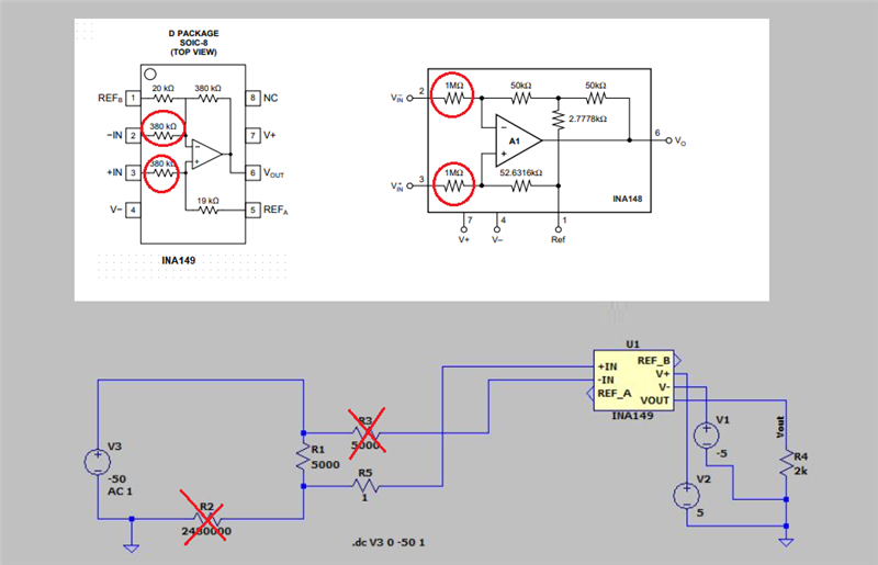
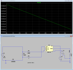
My LTSpice sim of the models provided by TI for the INA149 do not work. I use the models for your INA148 and they work just fine, but not the INA149s.

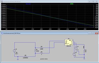
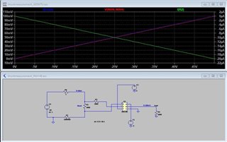
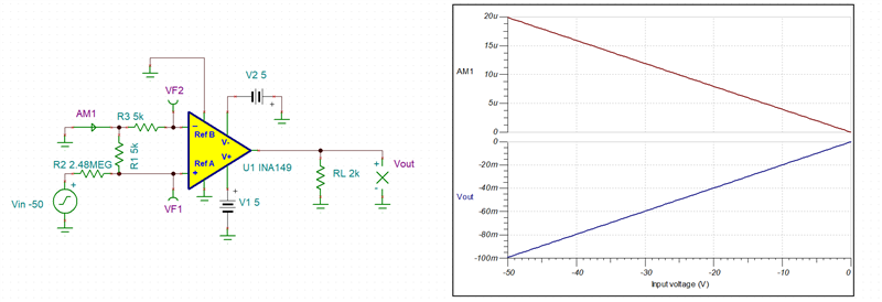
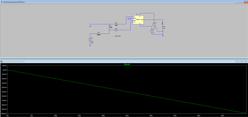
The circuit runs 0-20uA thru the R1 shunt resistor, producing 0-100mV.  Then the unity gain INA149 should produce 0-100mV at the output Vout.  Simple.  Like I said, if I replace with the INA148 model, it works perfectly.

  • Here is the INA148 working like it should.  Same circuit.  Output goes 0-100mV while input goes 0-20uA.

  • Hi Lou,

    Adding resistors in front of difference amplifier like INA148 (1M) or INA149 (380k) increases the value of the total input resistance causing error in both circuits. The only difference is that the error will be smaller in case of INA148 because of higher values resistors.

  • Well. as I said the INA117 which has the same resistors as the INA149 works just fine.  I don't believe these resistors are the problem.  If you look at the INA149 output its really just sitting at the same output (+/-1mV).  Something is wrong I believe.  Otherwise, why does the INA117 model work?

  • LTSpice is NOT fully compatible PSpice simulator and requires special conversion of the PSpice netlist before it can be used.  Using attached Tina-TI gives exactly the same results for both, INA148 and INA149 - see below.  

    Lou INA149e.TSC

    Or please try to use attached PSpice netlist with LTSpice - see below.

    6825.INA149.lib

  • Marek, Thank you for the help.  I figured it probably worked with Tina-TI but I am more familiar with LTSpice.  I tried the PSpice netlist you provided but it did not work either.  I think I will give up trying, as I don't know how the fix the model.

  • Lou,

    Sorry but we don't support LTSpice.  If there's any way we can help with our simulators, then let us know.

    Regards,
    Mike

  • Lou,

    A follow-up here - our modeling team advised me that the latest models on PSpice for TI should work fine.  If you can install or update the latest version of PSpice for TI, these should all work on most PSpice platforms with no problems.

    I attached the latest version here, let me know if this works.

    Hope this helps,
    Mike

    8547.ina149.lib

  • Michael,

    It still doesn't work on my LTSpice. Same result as before.  Curious because all the others (117, 148, etc.) work fine in the same circuit.  Some competitors work also, using the same type of op amp.  The INA149 is my favorite spec wise, but I just can't get it to work in my model.  I will try loading and learning PSpice for TI if I get a chance.  

  • Lou,

    There is a world of difference between INA117/INA148 and INA149 models.  INA117 and INA148 use an old Boyle model while INA149 is based on our modern, sophisticated behavioral Green-Lis or GWL architecture.

  • Marek,

    So what are you suggesting?  I think that people will try to use your new model(s) in LTSpice, and probably already have.  Do you know if they usually work?  Or do they not?  LTSpice is fairly popular in my area.  I do want to use the INA149, but I wish I could simulate it and compare on what I know, and that is LTSpice.  Like I said, if I get some time I will try and learn PSpice for TI.  However, I wonder if it only works with TI models?

  • Also, your free PSPICE for TI links don't work.  It puts you in an endless loop of filling out your personal information over and over again and never lets you download it. 

    Frustrating to say the least.

  • Lou,

    As Mike previously mentioned, for obvious reasons we do not support LT Spice. Having said that your faulty simulation results might be related to the pin order of the LIB file and associated symbol relationship being mismatched. You should dump the simulated netlist and compare it against the LIB file pin order - there seem to be a conflict between two of them.  If you cannot figure it out, please send me LT Spice schematic by attaching it to your reply: use INSERT -> Image/video/file located below active window.

  • Marek,

    Yes, I suspected that there was something wrong with the symbol pin order.   I did look at the netlist file to try and sort it out, but didn't notice anything.  What did you find?  I don't claim to be able to generate spice .lib s.

    I noticed that your older version has a different arrangement than the new one.  I've tried both .lib files however and neither work.  I've already attached my schematic earlier in this thread.  Its just a jpg of it.  If you want the actual LTSpice file I can send it as well?

    Lou

  • Yes, in order to debug it we need actual LT Spice schematic and not jpg.

  • Your Insert Image/Video/File will not insert my LTSpice .asc file.  What to do?

  • I sent you a separate message what to do.

  • Where? In my email?

  • Lou,

    Changing the schematic to the way you had originally show results in correct output - see below. Followed through the LIB import into LTSpice and autogenerated the symbol.  The LIB file was taken from the PSpice link in the TI PF.  Below I have attached LT Spice files.

    Thus, the issue must be in the way you set up your LT Spice files. If you continue having problem, you need to ask Linear Tech (ADI) for assistance.

    1122.INA149.lib

    https://e2e.ti.com/cfs-file/__key/communityserver-discussions-components-files/14/INA149.asy

    https://e2e.ti.com/cfs-file/__key/communityserver-discussions-components-files/14/shuntmeasurement_5F00_INA149.asc

  • Lou,

    I cannot send you the LTSpice files thru email - it gets rejected (see below).  But I attached the files in this post - see above.

  • Marek,

    Not sure why, but your files don't work any differently than mine.  I do not get the 0-100mV that you show.  I noticed that your symbol is quite different than what I get using the Autogenerated Symbol from LTSpice.  Did you modify the symbol before saving it?  The symbol file you sent me does not look like your picture above when I look at it.  The arrangement of the pins is completely different.

    I even updated to the latest version of LTSpice.

  • Lou,

    It is our modeling engineer that confirmed that your circuit does work correctly in LTSpice.  The symbol shape does not matter (it's just graphics) - what matters is the proper hierarchy and pin order.  At this point it is clearly an issue with your setup of LTSpice files - please contact ADI (Linear Technology) for further assistance. 

  • Marek, Thank you for trying.

    Lou

  • No problem.  I'm sure LT support can solve your problem.  Good luck.