Hi,
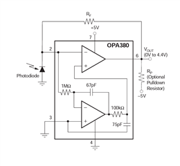
I was studying about transimpedance amp and came accross this IC. In the datasheet, there is a circuit which is intriguing me.

On the first page I came across this circuit which, as per my knowledge, is a simple transimpedance circuit with a small bias voltage at non-inverting pin of top opamp (to prevent opamp going into saturation)
(prior knowledge is based on video by TI on youtube: www.youtube.com/watch
But with this knowledge I am unable to infer what voltage will be developed at non-inverting pin of top opamp. The 1Mohm and 67pF forms an integrator circuit, which is basically a low pass filter with cutoff 2.3KHz and then followed by 100kohm and 75pF which again forms a low pass filter with cutoff 21.2Khz.
I am not able to understand the fact that how does taking voltage at photodiode and passing it with two low pass filter and giving it as a Bias voltage helping? Could anyone give me the proper explanation, it will be very helpful!!
Thanks


