This thread has been locked.

If you have a related question, please click the "Ask a related question" button in the top right corner. The newly created question will be automatically linked to this question.

OPA145: Charge amplifier for piezo sensors - weird output at low gain

Part Number: OPA145
Other Parts Discussed in Thread: OPA2991, TL072,

I'm trying to simulate a charge amplifier in LTSpice to be used with a piezoelectric sensor in audio range.

Here are the resources for charge amplifiers:

https://en.wikipedia.org/wiki/Charge_amplifier

https://www.allaboutcircuits.com/technical-articles/how-to-design-charge-amplifiers-piezoelectric-sensors/

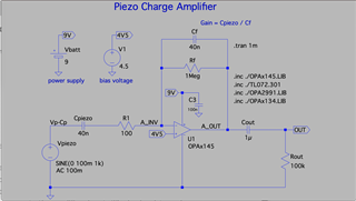
Charge amplifier is basically an integrator. I modelled the piezo sensor as a voltage source with series capacitance. Gain of charge amplifier is determined only by the ratio of Cpiezo / Cf. I'm trying to use OPAx145 - latest SPICE model (rev. C) from TI product page.

Here's my schematic:
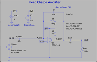
This means the amplifier has gain of Cpiezo / Cf = 40nF / 10nF = 4. With this setting, the output is correct, as follows:
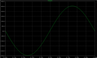
However, when I change the Cf to 40nF, thus setting the gain to 40nF / 40nF = 1, this is the output I get:
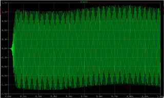
By choosing different values of Cf, I discovered I'll get similar crazy outputs with Cf > 11nF, i.e. every time the gain is < 4.

However, if I change the Cpiezo to 4nF and Cf to 4nF, i.e. the gain of 1, but with lower capacitances, I get a correct result (100mV sine wave on output).

If I use old TL072 model instead of OPAx145, any values of Cf or Cpiezo seem to give normal (expected) results. Similarly with OPA2991 model (which is a CMOS opamp, so maybe not directly comparable). I also tried OPAx134 - expected results too.

I'm attaching my LTSpice project with opamp models.

What property of OPAx145 is causing this? Or is something wrong with my simulation? Thank you!

charge_amp.zip

  • update: I just found out that inserting a 100ohm resistor in series between Cpiezo and inverting input solves this problem. But can anyone please explain why?

  • Hi Juraj,

    Looks a lot like instability but I'm not sure why the other devices do not show it.  There are many differences in BW, output impedance, model parameters, etc. that could be the culprit.

    We should be able to narrow this down tomorrow, please give another day for this.

    Thanks,
    Mike

  • Hi Duraj,

    Operational amplifiers are sensitive to capacitances placed right at the inverting input terminals of the op-amp device, and sensitive to large capacitive loads as well.  There is a video series Tutorial on TI Precision Labs that discuss op-amp stability, stability analysis and compensation. See below:

    https://www.ti.com/video/series/precision-labs/ti-precision-labs-op-amps.html

    Under Topics, search browse to "Stability" and there are seven sessions discussing op-amp stability.


    To answer your question, on the circuit above, the culprit causing instability is the Cpiezo=40nF capacitance.   The output load capacitance, Cout, is in series with a large Rout 100k resistor, therefore, the output load is not causing stability issues.  The OPA2991 (4.5-MHz) and OPA145 (5.5-MHz) amplifiers have similar bandwidth, but the open-loop output impedance characteristic over frequency is different.

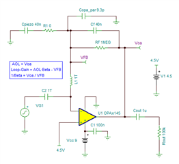
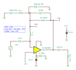
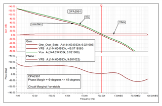
    The OPA2991 and OPA145 models both simulate accurately AOL, and open-loop output impedance to allow accurate stability analysis.  On the original circuit, with Cpiezo=40nF, CF=40nF capacitance, actually, both circuits show sensitivity to the Cpiezo = 40nF input capacitance: The OPA2991 circuit is at the edge of becoming un-stable, with very marginal or low phase margin of only 9-degrees, while the OPA145 is completely unstable with no phase margin.   

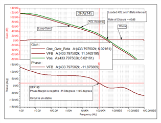
    For example, if we perform open-loop stability analysis of the OPA145 circuit, with CF=40nF, and Cpiezo = 40nF, the open-loop stability analysis shows negative phase margin of -11.8-degrees, meaning the circuit is unstable.  If we take a look at the simulation results, the open-loop output impedance of the OPA145 interacts with the feedback components, and the Cpiezo input capacitance, creating a second pole on the loaded AOL around ~120-kHz, creating the instability.  Due to this second pole on the loaded AOL, the intersection of the loaded AOL and 1/Beta have a -40dB rate of closure, making this circuit unstable. This unstable result correlates with your OPA145 transient simulation results showing oscillation/instability.


    TINA simulation: 7026.OPA145_forum_10-17-23_open-loop_stability.TSC

    Similarly, when we perform open-loop stability analysis of the OPA2991circuit, with CF=40nF, and Cpiezo = 40nF, shows only marginal 9-degrees phase margin, meaning the circuit design is not robust, the OPA2991 circuit is also marginal or at the edge of instability: 

    TINA file: 7026.OPA2991_forum_10-17-23_open-loop_stability.TSC

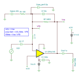
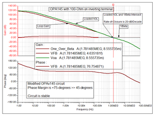
    There may be different ways to compensate the circuit.  However, in this case, since this is an integrator circuit that requires CF=40nF and the piezoelectric capacitance is 40nF, you are correct that adding the 100-ohm series at the op-amp inverting terminal stabilizes the circuit.  The 100-ohm adds a zero on the Loaded AOL frequency response cancelling the second pole that was causing the instability, where the Loop-Gain and AOL Rate-of-Closure where the AOL and1/Beta curves intersect is now around -20-dB/decade, making the circuit stable. The second circuit you have suggested with the 100Ω is stable with 75+ degrees of phase margin; and remains stable as you change the feedback capacitor.  See below:


    TINA file: 1641.OPA145_forum_10-17-23_100ohm_open-loop_stability.TSC

    Thank you and Regards,

    Luis

  • Luis, your answer is amazing - thank you so much for all the time and effort you put into such a detailed and clear explanation! And also for your own simulations and graphs. I certainly learned a lot, and will definitely watch the recommended video series. Much appreciated!

  • Hi Juraj,

    Thank you, let us know if you need anything,

    Kind Regards,

    Luis