Suppose I have an input signal that is a square wave from 0 to 5v at frequency of 1kHz. How would i average it out so i get 2.5V steady state (almost) dc
This thread has been locked.
If you have a related question, please click the "Ask a related question" button in the top right corner. The newly created question will be automatically linked to this question.
Suppose I have an input signal that is a square wave from 0 to 5v at frequency of 1kHz. How would i average it out so i get 2.5V steady state (almost) dc
See the Active Low-Pass Filter Design application note. How much do you want the 1 kHz wave to be attenuated at the output? Higher-order filters react faster to changes at the input.
If you know that the input has these parameters, then you also know that the output is a 2.5 V DC signal, and you do not need a circuit. What is the actual range of input voltages/frequencies/duty cycles?
Hey Jenil,
I agree with Clemens' comments above. In a typical PWM-DC you would use an RC circuit to average your PWM circuit. For this case, you want roughly -6dB at 1kHz. You can accomplish this with a basic RC filter.
If you would like to further filter this, or you can add a higher order filter mentioned above. Doing this in stages as well can allow you to get smooth voltage transitions.
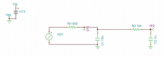
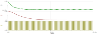
For example, to take a 5V, 1kHz PWM with a 20% duty cycle to a stable analog value, you can use the following circuit. This will settle the voltage to about 1V. The first RC filter sets your voltage level the second smooths out the value at the cost of response time (it takes about 40msec to settle to the final value)
Without the 2nd RC filter, the signal varies slightly around the target value. You can use an amplifier to buffer the output of this filter if you need to sink any current from this 2.5V value, as loading that node discharge the cap and influence the value of that node. I've included my simulation file if you would like to tweak the values.
Best,
Jerry