This thread has been locked.

If you have a related question, please click the "Ask a related question" button in the top right corner. The newly created question will be automatically linked to this question.

TLV3801: AC Coupled Differential output

Part Number: TLV3801
Other Parts Discussed in Thread: LMK00301

Hi team,

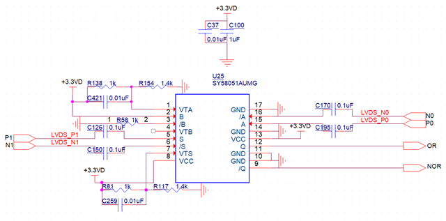
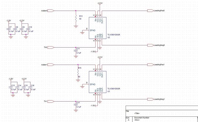
One of our customers uses the TLV3801 comparator for AC coupling output, the circuit is as follows, but the output waveform is abnormal and the waveform is as follows.

There are a total of 16 TLV3801 chips, and the network label can be ignored, as the TLV3801 and SY58051AU are separate sub-module designs. Not sure if the output waveform is related to the interconnections between the boards.

The next stage circuit of the TLV3801 is SY58051AU. SY58051AU datasheet:SY58051AU.PDF
abnormal waveform:
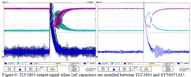
The DC coupling output is normal, i.e. remove the AC coupling capacitance, disconnect the SY58051AU and install a 100 ohm resistor between OUT+/-. The measurement TLV3801 output is OK: 

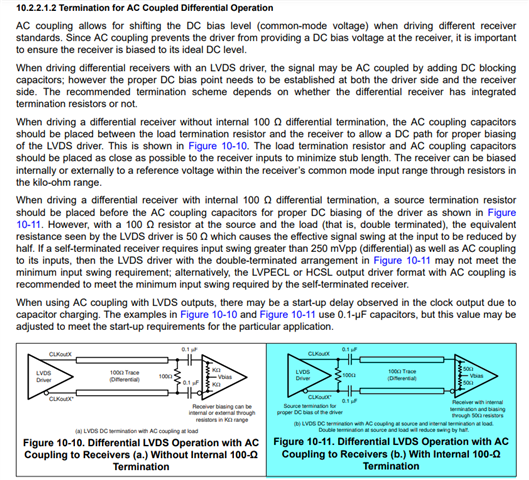
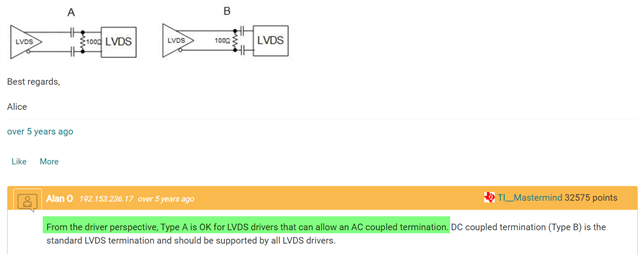
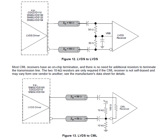
The customer refers to the application report below to connect the circuit. I also found the circuit for the LMK00301 datasheet section below, not sure why it is different from the circuit in this application report. 

AC Coupling Between Differential LVPECL, LVDS, HSTL and CML (Rev. C)

Could you help please analyze why the TLV3801 cannot have an AC coupled output? And why is the circuit connection recommended in this application report different from that in the LMK00301 datasheet? Could you please leave your comments
Best Regards,

Amy Luo

  • Hi Amy,

    Thanks for your post. TLV3801 should allow to ac couple the output, we do that here in our EVMs shown here: TLV3801EVM User’s Guide (ti.com)

    How are you terminating the scope when you look at the outputs? Is it 50 ohm terminated? 

  • Hi Chi,

    Thank you for your response.

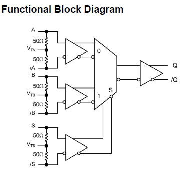
    The internal diagram of the receiver SY58051AU is captured below and incorporates a 50Ω resistor.

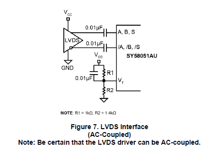
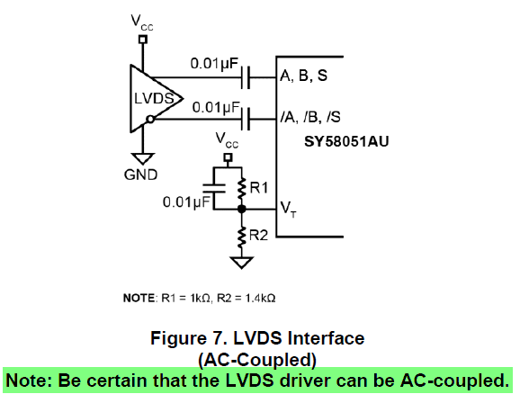
    The recommended connection circuits for SY58051AU datasheet are as follows:(VT is its internal bias voltage)

    When 50 ohm is terminated inside the receiver, is the termination resistance no longer required for the oscilloscope measurement?

    Best Regards,

    Amy

  • Hi Amy,

    It seems like the correct configuration may be adding the 100 ohm resistor before the ac coupling  capacitors to allow for proper DC biasing, like Figure 10-11 (the one in blue) in your initial post. However, as mentioned, you would run into double termination both at the source and the load. You could try using a 1kohm resistor at the output of the comparator before the coupling caps to provide the necessary output DC current path while avoiding double 100 ohm termination . However I have not confirmed if this would work specifically with the TLV3801 yet.

    These threads are similar in what you are asking for as well.

     LMK00306 - LVDS AC coupling termination method - Clock & timing forum - Clock & timing - TI E2E support forums 

    (+) LMK00304: Input LVDS AC Coupling - Clock & timing forum - Clock & timing - TI E2E support forums

    The ones in that application report says that it assumes the receiver does not have internal termination 

  • Hi Chi,

    In this customer application, SY58051AU datasheet also describes "Be certain that the LVDS driver can be AC-couple." So for an LVDS driver, how to determine if it allows an AC coupled termination? 

    From the EVM, the TLV3801 allows AC coupling output, but from customer test results, why is it not working as a Type A? 

    For the oscilloscope measurement, the customer is using the probe input impedance 1Mohm. P/N for differential pairs are measured separately with single-ended probes and do not use differential probes.

    Regards,

    Amy

  • Hi Amy,

    What is the frequency of the input signal? I am wondering if the ac coupling caps are actually not big enough to accommodate for some of the low frequencies.. Is it 1 nF or 0.1uF? Either way, what does the output look like if you increase them to say 200nF or 500nF?