This thread has been locked.

If you have a related question, please click the "Ask a related question" button in the top right corner. The newly created question will be automatically linked to this question.

LMH6551Q-Q1: LMH6551Q-Q1 Headroom Range

Part Number: LMH6551Q-Q1
Other Parts Discussed in Thread: THS4541-Q1, THS4531, THS4541, TINA-TI

Hi Team,

Was checking the Headroom for LMH6551Q IC and found that it was 1.31V for maximum supply voltage.

If I'm using a single 5V supply what is the headroom one should consider on the positive and negative output.

Hope 1V on the negative side should be fine, Please confirm

Thank you 

Niranjan T

  • Hello Niranjan,

      For 5V supply, I would use the specifications noted under 5V Electrical Characteristics Table (pages 5 and 6). 

     Output Voltage Swing is specified as +/-2.5V peak to peak voltage of +/-2.8V typically. This denotes OUT+ terminal = +1.4V & OUT- terminal = -1.4V at a split supply configuration. To convert to single supply of 5V, you would take 2.5 - 1.4V which is equal to 1.1V headroom from either supply. In other words, this could also be interpreted as the output swing on single-ended output is limited to approximately 1.1V lower than V+ or 1.1V higher than V-, and is irrespective of whether the supply is +/-2.5V or +5V as long as the Vcm is set to mid-supply which is 0V for +/-2.5V and 2.5V for +5V. 

      Therefore, 5V at 2.5V Vocm would give you a headroom of 1.1V to 3.9V typically. 1V would fall slightly below this range which can place the amplifier in non-linear operation, but we can help suggest another amplifier. Do you require an automotive grade device?

    Thank you,
    Sima

  • Hello Sima,

    Thanks for your inputs, can you also just let me know what would be the case if Vocm is not set to 2.5V. For example if I set my Vocm to 2.1V will my headroom voltage still remain the same(1.1V to 3.9V) for 5V single supply.

    And also suggest me Amplifier which can have a voltage of 1V or below as the headroom, The suggested Amplifier should be an AEC qualified part. Awaiting your response at the earliest.

    Thank you

    Niranjan T

  • Hello Niranjan,

       With Vocm set to non mid-supply, most likely yes, around 1.1 to 3.9V; however, it is not guaranteed. 

       I would recommend the THS4541-Q1; it can be operated at 5V single supply within 200mV from either supply: 0.2V to 4.8V. Its other specifications are an improvement over the LMH6551Q except with a slower slew rate.

    Thank you,

    Sima 

  • Hey Sima 

    Thank you for the part suggestion, In my application I wanted to have the differential Input to the Amplifier of 2V p-p. Just while going through the datasheet in page 4 I came across the data saying Differential input voltage Max of ±1V. So is it saying that I cannot provide a 2Vp-p to the input of THS4541-Q1.

    In my application the inputs are 180deg out of phase, each input is 2V p-p. Will this be acceptable by the THS4541Q. 

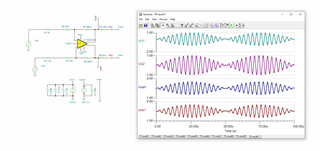
    Also attached simulation file. please let me know would that work.

    Resolver_THA4541.TSC

    Also the spice model is for THS4531, is it the same spice model for THS4541.

    Thank you

  • Hello Niranjan,

      The max differential input specification for our amplifiers refer to the voltage differential directly at the IN+ and IN- node. Your differential input voltage will measure lower due to the resistive network. 

      VF1 and VF2 will be your input voltage range which should be within specified in the THS4541-Q1 datasheet: -0.2 to 3.8V, and Vdiff is the input differential specification. 

      THS4531 is not the same spice model as THS4541, you may use THS4541 Spice model which is the same as THS4541-Q1. This is located on each device's product folder under design&development tab. Below is a downloadable link to the Tina-TI reference circuit of the THS4541. 

    6428.sbom907b.tsc

    Thank you,

    Sima 

  • Thank you Sima for your support on this Issues.

    Niranjan T