This thread has been locked.

If you have a related question, please click the "Ask a related question" button in the top right corner. The newly created question will be automatically linked to this question.

OPA548: How much capacitance could OPA548 drive?

Part Number: OPA548

Dear product line

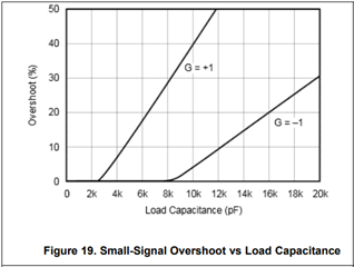
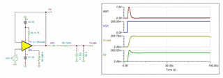
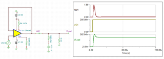
one issue need consult here. my customer want to design a adjustable negative LDO in range -0.8V~-8.5V with ~2A. there is no LDO could output low -0.8V. so my idea is to use TI power amplifier to meet customer requirements such as OPA548 or similiar parts. but my concern is the amplifier may potential unstable if the load capacitor larger than specific value. as you know there may have lots of capacitor for buffer in power line. could you please suggest maximum cpacitor that OPA548 supporting?  Could customer series a resistor in feedbackloop for stable under large capacitor load?  thanks.

regards,

Bill      

  • Hi Bill,

    Figure 19 of the OPA548 datasheet shows the % overshoot vs load capacitance for the OPA548. For small-signal applications an overshoot of 20% is considered stable, however for your linear power supply you may want to keep the overshoot near zero.

    Since you want to output a negative voltage anyway, you may use the inverting configuration as this will allow you to drive more load capacitance with minimal overshoot (up to 8nF for G = -1 V/V). As you are creating a linear power supply, you may not require the same high bypass capacitance that is common for switching supplies to suppress the voltage ripple.

    Alternatively, you can place a large capacitance at the output and use a small isolation resistor to stabilize the amplifier. The larger the capacitive load the smaller the isolation resistor needs to be for stability. You can take advantage of this to reduce the power dissipation through the isolation resistor. If additional capacitance is added downstream, the amplifier will still maintain stability.

    Another option is to configure the isolation resistor in series with the capacitance but parallel to the load as shown below. This will reduce the steady-state power dissipation through the isolation resistor but causes some overshoot to occur at the load. This configuration may not maintain stability if additional capacitance is added to the output downstream without additional isolation resistance.

    Note that the large capacitance values above result in large RC time constants that greatly limit the response time of the linear power supply. Depending on your speed requirements you may need to ensure a minimal load capacitance.

    Regards,

    Zach