This thread has been locked.

If you have a related question, please click the "Ask a related question" button in the top right corner. The newly created question will be automatically linked to this question.

An alternative to ths7347/ ths7327

Other Parts Discussed in Thread: THS7347, THS7327, THS7353, TVP7002, THS7303, THS7368, THS7364, OPA3690, OPA3693, OPA3695, OPA2830, SN10502, SN10501

Hello,

Can anybody please tell me of an alternative to THS7347/ THS7327 buffers. Actually i need to use an RGBVH buffer for an xga signal and then input the buffered output  to TVP7002. Got to know about THS7347 and THS7327 but the problm is that these are non-stock. I have gone through THS7353 's datasheet but i think it cannot be used for XGA with separate sync.

Please let me know about about an RGBVH buffer thats easily available

Thanks in advance

Easlkhn


  • Easlkhn,

    I just checked some distributors stock, such as DigiKey, and there is some stock of both the THS7327 and THS7347. If you can share with me more info about how many parts are needed and what distributor you utilize, I may be able to help out.

    As for some alternatives, XGA (1024 x 768 x 60Hz) needs a bandwidth of about 52MHz and a slewrate of about 291V/us (VESA specs). With this in mind, the THS7353 (or even THS7303) in bypass filter mode can support this.

    If a filter is desired, then the only other alternative is a part like the THS7368 or THS7364 (right now anyways with a new part 4-ch coming shortly).  These have a gain of 2V/V but this can be reduced by simply using a resistor divider after the amplifier (or at the input if desired).

    There are several other considerations, such as single supply vs dual supply, or is an input MUX needed, but I would need more information to help out.

    Cheers,

    Randy

  •  

    Hello Randy,

    Thanks alot for ur help.

    Actually i m working on a project to capture three simultaneous XGA signals. I have figured out that i'll have to use rgbvh buffers, TVP7002 and DM6467 in order to achieve this.

    Please note that i cant use composite or sync on green. My xga signals are 5 wired RGBVH. Before inputting to TVP7002, i think i should use a video buffer like THS7353. But i think THS7353 can be used for PC signals with sync on green only whereas my xga input signals are separate sync(5 wired).For this reason i searched and found out that THS7347 can be used.

    Multiplexing is required as there are three XGA signals that need to be buffered. I think I'll have to use two THS7347. One with two XGA's and the other with one xga connected to it. Is it?

    Does THS7353 can be controlled using I2C in such a way that the XGAs at the ouput of THS7353 appear to be simulateous Or should i go for three THS7353 , one independently working for each XGA?

    Thanks and Regards,

    Easlkhn


  • In the last part of my previous post i mistakenly wrote THS7353 instead of THS7347. I actually wanted to ask

    Can THS7347  be controlled using I2C in such a way that the XGAs at the ouput of THS7347 appear to be simulateous Or should i go for three THS7347 , one independently working for each XGA?

    Regards,

    Easlkhn


  • Because you want to do simulataneous acquisitions, and the fact that the MUX's are controlled via 400kHz I2C bus rates, I would recommend that you need to have seperate components.

    There are other options that may make sense including, but not necessarilly limited to:

    a) 3x  THS7347 - Great if you want to have a pass-thru function - recommend to use 5V to support 5V HV sync logic (or use a divider on the inputs to handle 5V logic)

    b) 3x THS7353 in bypass mode + simply connect the HV sync to each TVP7002 or use a Logic buffer to buffer the sync's (be sure it is 5V tolerant).

    c) 3x OPA3693(Configured for G=1V/V, requires +/- 3.3V or +/- 5V supplies)  + HV sync configuration as above; could use OPA3690/91/92 but OPA3693 is the fastest.

    d) 3x THS7364 (or our new 4-channel version releasing later this week) - simply not use (shutdown) the SD channels. +  HV sync configuration as above

    Hope this helps.

    Cheers,

    Randy

  •  

    Thanks alot for your time and help Randy. I am definitely goin to adapt one of the valuable suggestions you gave.

    Regards,

    Easlkhn

  • Hello Randy,

    I think  using OPA3693 will be more appropriate in my case as now i have come to know that my input signals are differentail RGBVH.

    Please tell me that if my RGBVH, all signals are differential, can i use OPA3693 in order to achieve buffered (G=1V/V)  as well as single ended output?

    If this is correct, For each xga signal i'll have to use 2x OPA3693, one for differentail RGB signals and the other for differential H and V syncs (making a total of 6x OP3693 for thrree Xgas). Is it? Would you recommend Same configurations for both OPA3693, one used for differential RGB and the other for differentail H and V sync.

    Regards,

    Easlkhn

  • Easlkhn,

    The OPA3693 can make a very good differential amplifier as ling as the desired gain needed is 1V/V. If more gain is needed, then you would need to go to a part like the OPA3695 for the feedback resistor flexibility. Ofcourse, using +/-5V supplies is desirable for these parts due to architecture in them.

    As for the HV Sync's, the OPA3693 could also work, but it seems a bit overkill. Some alternatives include OPA2830 or SN10502 (linear solution) or even a dual comparator (not sure which one(s) but there are several choices within TI).  Because H and V sync is only "logic" then maybe a comparator can work well. But, if the reason for differential inputs is due to common-mode noise rejection, then using a linear opamp solution may be best. I recommend using at least +5V and GND supply, or +/-5V supply can also work well.

    Cheers,

    Randy

  • Hello Randy,
    Thanks for ur help.
    Can u please tell me how to use SN10502 for differential H and V syncs?
    I have gone through the datasheet of SN10502 and found out that all video applications employ either applying input at
    the inverting terminal or at the non-inverting terminal. And hence, all the resistors and capacitors have been chosen accordingly
    in order to achieve the desired gain.
    However, i need to use both the differential inputs of each of the sync ( H+, H- for horizontal sync and V+,V- for vertical sync)
    in order to convert differential to single ended and achieve a gain 1V/V. What configuration i should go for, connections,
    resistor and capacitor values?
    Waiting for your reply.
    Regards,
    Easlkhn
  • Easlkhn,

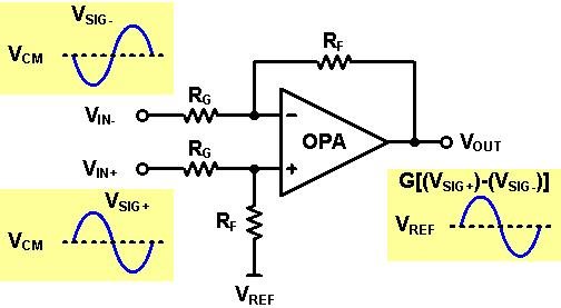
    Bellow is a common op amp circuit that is used to convert differential signals to single-ended and provides gain (or attenuation) and level shifting. 

    If we set VIN+ = VCM + VSIG+ and VIN- = VCM + VSIG-, then
    Vout = ( VIN+ - VIN- ) x RF/RG+ VREF

    The signal gain of the circuit is set by: G = RF/RG , VCM is rejected, and VREF provides a level shift around which the output signal swings. The single ended output signal is in-phase with the differential input signal.

    Line termination can be accomplished with a resistor shunt across the input. The impedance seen differential from the line will be the resistor value in parallel with the amplifier circuit. For low gain and low line impedance the resistor value to add is approximately the impedance of the line. For example if 100Ω CAT5 cable is used with a gain of 1 amplifier and RF = RG = 1 kΩ, adding a 100Ω shunt across the input will give a differential impedance of 98Ω; this should be adequate for most applications. For best CMRR performance resistors must be matched. A rule of thumb is CMRR the resistor tolerance; so 0.1% tolerance will provide about 60dB CMRR.

    From SN10501 data sheet RF = RG = 1 kΩ look like good values to use to set gain and should not need other capacitors except bypass capacitor (0.1uF) and use 25Ω to 50Ω series output resistor for best pulse response.