This thread has been locked.

If you have a related question, please click the "Ask a related question" button in the top right corner. The newly created question will be automatically linked to this question.

ECG with Ina116

Other Parts Discussed in Thread: INA116

Hi,

I am trying to amplify the differential signal with the ina116. I am also trying to find the input impedance of LM741CN op-amp at the same time. Here is what I did so far;


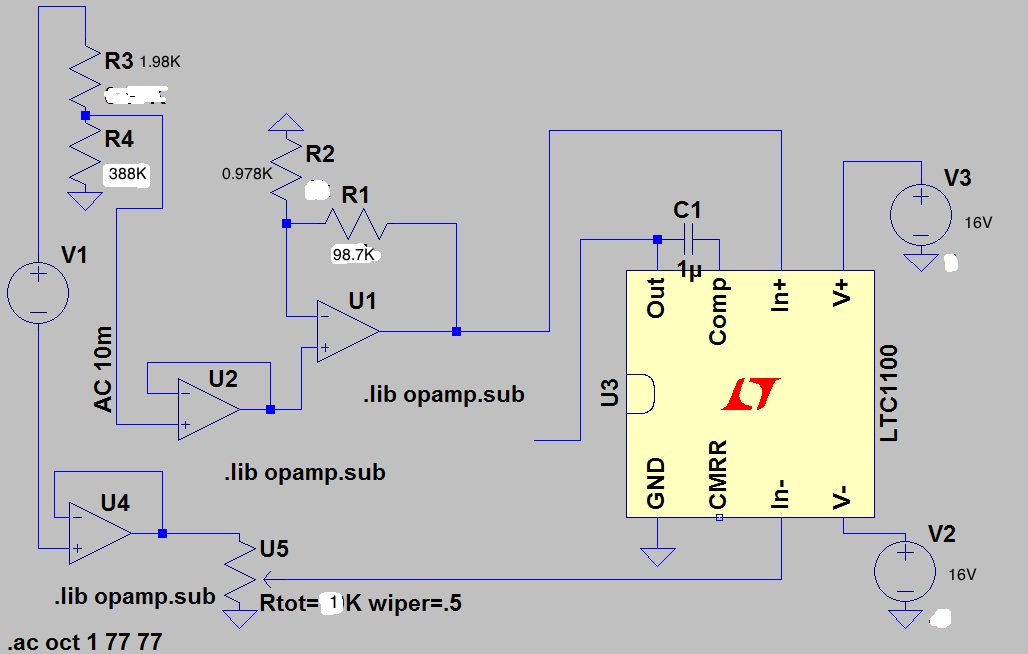
My signal source is connected to a voltage divider that has an output of around 21mV p-p. Voltage divider's output is connected to an non-inverting amplifier with a gain of around 100 so the output of the NI amp is 2.08 p-p and this is connected to -ve input of ina116.

The same signal source also connected to a buffer amplifier and its output is connected to a potentiometer which has an output of 2.08V p-p. Potentiometer's output is then connected to +ve input of the ina116.


Thus, I have almost the same voltage values for both inputs of the ina116 and as a result i should be having a zero volt at the output right ? However, I have an output of 2.48mV p-p and the waveform looks like a mixture of a sine and sawtooth signal.


When I change the output voltage of the potentiometer nothing happens on the output of in-amp. I configured the in-amp as it was shown in the datasheet. Does anyone have an idea of why I am not having an amplified differential signal when I change the voltage of the potentiometer ?


Regards


Caglar Sekmen

  • I forgot to mentioned that my signal source is around 4.00-4.06 V Peak to peak. And I configured to in-amp's gain as 1000.

  • Hello Caglar,

    Instead of a textual description of the circuit, can you please provide a detailed schematic and screen captures of the inputs and output of the INA116?

    I would also like to ensure that the INA116 is appropriate for your design.  Can you please tell us why you selected this device?  I would assume that it's for the extremely low Ib.  The drawback, however, is that such devices have larger offset voltages which generally mean use in lower gain applications.  You noted that the INA116 in a gain of 1000.  If you wish to look at alternate parts, please provide us with your criteria.  This would include information such as the given input signal (frequency, impedance), desired output signal, the load characteristics, available power supplies, etc.


  • Hi Mr. Semig,


    Today I got another INA116 to test because I was suspicious about the previous amplifiers output waveforms. Now with the new one I could able to see amplified differential signal with various gains (50, 100, 500 and 1000). I selected it because I will be designing a basic ECG amplifier circuits that were made by the INA116. I found 3-4 different designs and they had all INA116 at some point. I haven't decided which one I should design so if you have a suggestion, I would definitely consider it. The reason I constructed this circuit is that my supervisor asked me to find the input impedance of the LM741cn. Thus, the next step will be choosing a more sophisticated ECG design and measure the gain of the in-amp as a function of frequency. I think gain of 1000 can be a bit too much for this kind of applications right ? I decided to use 500 as I go along.


    I did this schematic below on LTSpice 4 and it is not quite right. I am using +/-16v power supplies for in-amp and LM741cn amplifiers. So the 5V on in-amp is not correct. Actually this is something I have been thinking about because I read posts and saw most of the people used less than 12 V. To provide enough power for all the amplifiers I had to chose 16 V at least. Do you think I should use less than this value for in-amp ?As you can see that the in-amp placed is LTC1100 but it is just to represent an in-amp so this is just to give the idea of my design.

    note: I have a 4.00-4.08 p-p input signal at 77 Hz. Also, I havent guarded the input pins and would like to know how it is done properly. Should I add a 10Mohm resistor to one terminal in series with the +/- signal.

    Regards

    Caglar Sekmen

  • Hello caglar,

    Thank you for the schematic…I will help the best I can.

    First, you stated that you’re trying to measure the input impedance of the LM741CN.  Though this is a National Semiconductor device, the value is listed in their datasheet.  I also seem to recall a fairly detailed academic analysis of the device in a textbook by Sedra and Smith.

    Concerning the schematic, please note that it shows both supplies connected to +16V instead of +/-16V.  The choice of power supply (as well as gain) depends on your application requirements.  Parameters such as output voltage swing and common-mode voltage range are affected by the supply voltage.  When selecting the gain of the device, ensure that you do not saturate the output.  Information for guarding the input pins is discussed in the INA116 datasheet.  I don’t understand the significance of placing 10Mohm resistor in series with the input.  A low-impedance source is preferred, though the datasheet does discuss how to connect the inputs to high-impedance sources.    

    I hope this information helps. 

  •  

    Hi Mr. Semig,

    Sorry about the schematic, I am using +/- 16 V for power supplies. Just forgot to write (-) sign in front of one.

    In LM741CN's data sheet, the input impedance was defined as 2 M Ohm.Firstly, to measure the offset voltage of the INA116, I grounded both inputs and measured the voltage at the output, which was around 13  mV (p-p). For Rg, I placed a 98,2 Ohm resistor ( gain of 500). According to offset equation in the datasheet, the offset voltage can be determined as +/- 2/G. Thus, I divided 13 mV by 2 as it was peak to peak and divided the resutl by 500 to calculate the offset voltage as 0.0132. Is this the right way of doing it ? I did this test on a different breadboard so there is no interferences from other components.

    Secondly, I placed back the INA116 to schematic above and tested the circuit without a test resistor in series with non-inverting amplifier's positive input and I could see the nice amplified sine voltage difference at the output of the INA116 with a gain of 100 (Rg=511 Ohm).

    However, when I placed a test resistor of 98.8 K, I suddenly had a totally different output waveform. I don't have the output waveform to post right now but I can provide it tomorrow. . Without the test resistor I was having 2.24 V p-p at the output of INA116. With 98.8K resistor, the output signal dropped to 2.24 mV and as I increased to resistor the output voltage increased slightly. I dont understand how a series resistor can change the output signal like this.

    Also, When I reached close to 2M Ohm for the test resistor, the output of the non-inverting amp reduced from 2.08 (which was stable until 2M) to 1.98 and kept reducing as I increase the test resistor. I was hoping to have an increasing waveform at the output of the INA116 as the -ve input was reducing while the +ve was same all the time but even though the signal difference between the +ve and -ve inputs was almost 0.7V, there was no change at the output at all. How come the output does not change as the differential voltage increases. How is this related to the input impedance of the non-inverting amplifier ? I know I am asking too much here, but I really want to understand the reasons behind these.


    Best Regards


    Caglar Sekmen