This thread has been locked.

If you have a related question, please click the "Ask a related question" button in the top right corner. The newly created question will be automatically linked to this question.

INA700: Earth resistance testing range

Part Number: INA700

Hi,

We are trying to design an earth resistance meter that forces a voltage across the earth resistance and measure the sense current, returning the measurement to an MSP430, which then outputs to a display.

We are planning to choose INA700 for the current sensing because of it's integrated high accuracy resistance and digital output which we can directly interface with MSP430, and the EVM is also designed to make the required firmware development and testing easier and low cost, making it a very appropriate choice.

Here are a few questions regarding the concept:

- The earth resistance can have a wide range from 100m ohms to 10 ohms, which means that the current through the INA will range from 100mA to 10A . How will the current sense accuracy vary over this range of currents?

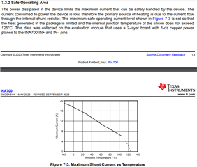
- 10A of current through 2m ohms of integrated resistance may cause internal heating due the 200mW of dissipated power. Is this a concern?

- Will the same concept work if we force a 2KHz sinusoidal voltage and measure the variable ADC output? Are there any issues that we may face while testing this concept with the MSP430 SCB and INA700EVM?

Thanks and best regards

Divyanshu 

  • Hello Divyanshu,

    I am looking this over and will respond shortly.

    Sincerely,

    Peter

  • Hello Valued Engineer,

    The best way to quickly calculate error at the low current is to calculate error due to offset, which is eIos_max = Ios_max/Ilow = 1.5mA/100mA *100 = 1.5%

    You can also assume a max 0.5% gain error (Gserr) at 100mA (see electrical characteristics table, Table 6-5 of datasheet). A RSS error will yield SQRT(1.5%^2 + 0.5%^2) = 1.581% total.

    At 10A current, the typical gain error is specified to +/-1.25%, but I would say it is safe to assume the max gain error at 10A could be +/-1.65% because there is also a 0.4% difference between typical and max gain error at 5A. Also see Figure 7-2 for more information. However, the eIos will be lower at higher currents. At 5A, eIos = 0.03%, thus total possible error at 100mA and 5A will be similar.

    This analysis does not include errors from offset or gain error drift, nor offset errors due to DC CMRR and PSRR.

    10A continuous current is safe for the device as long as the internal junction temperature does not exceed 125 degrees C and this will depend upon board layout and ambient temperature. Using the EVM as a reference point, we have characterized the following curve showing the maximum safe operating current over ambient temperature:

    The 2kHz sinusoid is within the BW limitation of the device assuming you choose a fast enough conversion time. Fastest conversion time is 50us, thus BW = (1/2)* 1/50us = 10 kHz. However, given the non-linearity in gain over current (Figure 7-2), this could result in non-linearity in the measurement of AC signal depending upon the signal amplitude. This should be considered when determining how to process the data. For example, maybe you would want to only process certain data points in phase (say whenever the signal is at it peak or trough when calculating resistance.

    Please post back with any follow up questions you may have.

    Sincerely,

    Peter

  • Hello Valued co-engineer,

    Thank you for your time and valuable inputs. I don't have any more questions for now, so I will let my other team member ask questions if any.

    I may get back to you with other specific issues that I may face while developing this concept using MSP430 SCB and INA700 EVM.

    Thank you very much for your support! It is greatly appreciated.

    Kind regards

    Divyanshu 

  • Hi Peter,

    I am unable to access the EVM GUI through the link provided in the user's guide: https://dev.ti.com/gallery/info/

    Is this the same as: https://dev.ti.com/sysconfig/index.html?product=ascstudio&module=/ti/sensors/currentsensor/INA700 ?

    Thanks and regards

    Divyanshu

  • Hey Divyanshu,

    The link should be updated to:

    https://dev.ti.com/gallery

    A search for INA700 yields:

    https://dev.ti.com/gallery/search/ina700

    There are three options (including what you mention), but they all should essentially be the same thing for INA700. However, the recommended version is the EZShunt-EVM-GUI.

    Sincerely,

    Peter