This thread has been locked.

If you have a related question, please click the "Ask a related question" button in the top right corner. The newly created question will be automatically linked to this question.

INA293-Q1: Noise Issues

Part Number: INA293-Q1
Other Parts Discussed in Thread: INA293

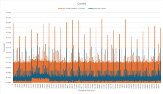
Hello, I am using INA293A4QDBVRQ1 in a design. I placed the current sense circuit near the power input so I can measure the current of the whole board. When I measured the current, I got very noisy data. I took a 4.02ohm resistor and external to the board, measured current. This data was much cleaner. I measured both the output of INA293A4QDBVRQ1 and external 4.02ohm current at the same time using NI-9205 sampling each channel at 100K samples/sec. Any ideas why this might be?

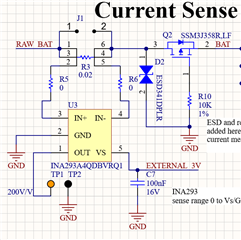
Here is the INA293A4QDBVRQ1 schematic
Here is the data collected. Orange = INA293A4QDBVRQ1, Blue = external 4.02ohm
 

  • Hello Tyler,

    I think you are operating it in the low range and not in the linear range of the device.  Swing low is about 20mV.  20mV/200(Gain) = 100µV at the input.  Meaning with the 0.02Ω the min current you can measure is 5mA.  You may need to increase your Rshunt.

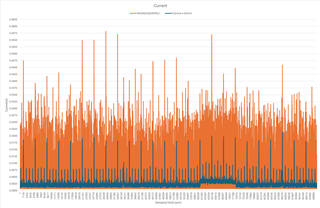
  • I replaced the 0.02Ω with a 0.2Ω. This seemed to help but did not full resolved the issue. It seems like it still has a bunch of noise at 10mA and below. I dont think im in the low range as that would be 500uA.

  • Tyler,

    Can you please give me your ADC information and how you are driving it?  Is it just and RC?   I assume it is a SAR ADC.  If you cannot share key items are sampling cap size, internal resistor, sampling time, conversion time and your external resistor or cap before the ADC.

    I am not sure if this is the issue or not.   https://www.ti.com/lit/an/sboa443/sboa443.pdf

    Regards,

    Javier Contreras

  • Javier,

    I am using an NI-9205 to collect the data. https://www.ni.com/en-us/shop/model/ni-9205.html I am connecting TP1 and TP2 directly to one of the differential channels on the NI-9205.

    Thanks,

    Tyler

  • Hello Tyler,

    So I calculated the noise expected from the INA293 and this does not add up, as it should be 1.57mA Peak to Peak noise.  The NI-9205 has high impedance and these instruments normally buffer the signal so my ADC drive information is irrelevant.

    The only thing I have left is the that the noise seen at the input is still causing the INA293 to go below the saturation point and not remain in the linear range.  This can be verified easily but may not be what you would like to do in your application.  Adding a resistor on R6.  Placing the R6 creates an offset due to the IB of the device.  This offset does change with input voltage so there will be a slight gain error if you stay in the 10Ω range.  Adding a larger resistor will give you a larger offset and a larger gain error.  

    If this is the case and the output will be that low you could get a bidirectional device so that your linear range near zero will always remain in the linear range.  Add a larger Rshunt resistor.   

    Regards,

    Javier