This thread has been locked.

If you have a related question, please click the "Ask a related question" button in the top right corner. The newly created question will be automatically linked to this question.

LMH6622: Questions of DRV2603

Part Number: LMH6622
Other Parts Discussed in Thread: THS4211

Dear Team,

Follow up this post:

https://e2e.ti.com/support/amplifiers-group/amplifiers/f/amplifiers-forum/1262043/lmh6622-questions-of-lmh6622/4779720#4779720

Regarding sin2sqr circuit, please see my feedback below.


1.Are you able to provide more details on what the application or end requirements are for this circuit.

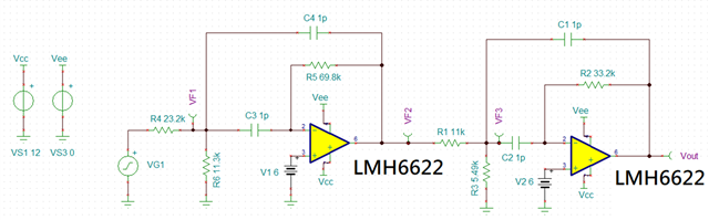
We've identified an issue with EMI radiation emission at low frequencies such as 30MHz, 50MHz, and 70MHz. This problem is caused by 10MHz clock harmonics. These harmonics only manifest in square wave signals, not in sine waves. As a solution, we will use this circuit to convert the signal.

  1. It is possible to generate a sine wave from a square wave, but you will face issues such as poor harmonic distortion performance and trying to get a very linear sine wave will also pose some difficulties. If you are able to provide more requirements you are looking to achieve, that would help identify the best solution.

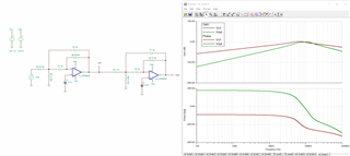
Our goal is to reduce the magnitude of the 10MHz clock harmonic. However, we are concerned that other low-frequency noise may be amplified, given that this is a low-pass filter and amplifier circuit. Do you have any suggestions for this circuit?


--- New question ---

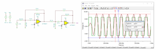
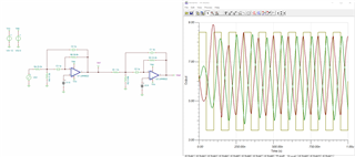
We observed a +/-6V waveform at the output side ("2") when injecting a 10MHz clock into this circuit at the input side ("1"). However, the output signal returns to +/-1.5V within a few milliseconds. Please provide guidance on how to resolve this issue. Thanks.

I am assuming that you meant the input could be from 1.2V-0V or 5.5V-0V. Is 50% duty cycle required? Yes.

Many Thanks,

Jimmy

  • Hi Jimmy,

    The easiest way to convert a square wave to a sine wave is to filter the square wave signal. Using a bandpass filter, the following can be achieved:

    Designing a filter with a center frequency of 10MHz and a pass band of 10MHz (pass band range of 5 to 15 MHz), the following circuit was generated.

    I replaced the LMH6622 with the THS4211 (as an example device, other higher bandwidth, higher slew rate devices can be dropped in as well depending on constraints). This is because the LHM6622 has a slew rate of only 80 V/us which distorted the sine wave signal. The THS4211 has a much higher slew rate and bandwidth so it is able to produce a cleaner sine wave. Is the LMH6622 the part that must be used in the customer application?

    Also, the noninverting input terminals have been biased at 6V DC and the input square wave was biased at 6V DC in order to operate within the input common mode range of the device for the supply voltages you specified.

    I have attached the simulation file below as well.

    THS4211_sqr2sin_E2E.TSC

    Does this meet the customer application needs? Please let me know if there are any other questions or concerns.

    Thanks,

    Nick

  • Hi Nick,

    One more question, could you recommend R/C value when using LMH6622 on your proposed band-band circuitry? Thanks.

    Many Thanks,

    Jimmy

  • Hi Jimmy, 

    In order to generate the same passband frequency response, you can use the same R/C component values as shown above. This will provide you with the same frequency response as I have shown below.

    However, as I stated previously, the bandwidth and slew rate limitations of the LMH6622 produce a much more distorted signal, as shown below.

    Thanks,

    Nick