A related question is a question created from another question. When the related question is created, it will be automatically linked to the original question.
If you have a related question, please click the "Ask a related question" button in the top right corner. The newly created question will be automatically linked to this question.
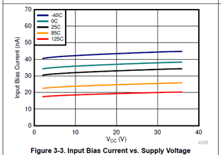
Where can i find input leakage current of LM2903-Q1. I could not find it in the datasheet. Kindly provide input leakage current of both inputs and its variation with temperature.
Do note that the LM2903-Q1 will be under PCN to change to a die similar to the LM2903B-Q1, which has 10x less bias current. So the non-B could be used as a worst-case. Please take this into advisement.
Thanks for the response. I am not looking for bias current information. Let me elaborate, when i say ''leakage current'' I meant when the comparator is in unpowered what is the current that is flown into the input pins. I hope I am clear.
With the power off, the input stage is a reversed biased BE junction. "Leakage' will be in the pA's at room temp, and increasing 10x every 10°C just like any PN junction leakage.
Power-off is not a valid operating condition, so we cannot give any limits...but it should be under a microamp at worst.
Thanks for the response. I know that operating LM2903B-Q1 during power-off condition is not desired. But in my application i have a capacitor at non inverting terminal which is charged to 10V and discharges through a large resistor in about 4-6 seconds after power off condition. so to understand the behaviour during this condition i want to know information of input leakage current. we usually get the reverse leakge current information in the datasheet for any P-N junction diode and its variation with respect to temperature. So I would like to know the similar information for the input terminals of this device as well.
We do not have that information immediately available, as this is not really a valid operating condition and we would not have tested for it specifically.
But we do know that the inputs look like a reversed biased diode and leakages would be less than a few nA at room temperature. It should not damage the LM2903 - but we do have to warn about applying a voltage to the inputs with no power.
We do recommend that a series resistance of a few kohms be added to the input to limit any currents "dumped" from the large capacitor should there be a fault or transient (latch-up).
I know its not a valid operating condition. But i want to understand how the input of this comparator behaves when there is a voltage present during power off condition. As per my application I have capacitor at the non inverting input pin which discharges through a large resistor when there is no power and the discharging current is of few uAs. To understand the discharging behavior i need to consider comparator input leakage current which has significant impact on rate of discharge and I am curious if the leakage current varies from nA to uA during power off condition at different temperatures(In my case -40c to +125C) since it will change my worst case calculations and Threshold voltage of inverting input.
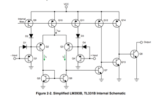
Also, I have looked at input stage schematic for LM2903B and it has a protection diode D4 at the input and it will be forward biased when Vcc is not present. Thats the reason i am little confused on what to consider for my calculations for the input leakage current. It will be good if you can provide estimated values for the same and its variation over the temperature range -40c to +125c.
With Vcc=0V, and a voltage applied to the input, D3 and Q3 are reverse biased, so current cannot flow. Q4 base will also be reversed biased, even if there was current flow somehow to ground, the base voltage would be higher than the emitter due to D4, creating a reverse Vbe and cannot turn on Q4. The node of D3, D4, Q3 and Q4 is essentially floating.
Normally we do not provide data for out-of-datasheet spec operation, but let me check if we can get a worst case estimate.