This thread has been locked.

If you have a related question, please click the "Ask a related question" button in the top right corner. The newly created question will be automatically linked to this question.

INA823: Warm-up drift and long-term stability

Part Number: INA823

Dear, Support Team.

One of our customers uses an INA823 with a gain of 201.
Does the INA823 have any secular variations in offset voltage, such as warm-up drift or long-term stability?
Customers may notice that the offset voltage shifts for about 20 minutes after turning on the power.
INA823 23110700_1-2-circuit diagram.xlsx

Best Regards,
Hiroaki Yuyama

  • Hiroaki,

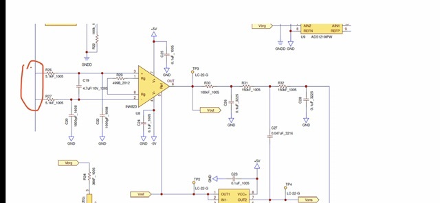
    Before I consider any other potential reason behind the INA823 initial input voltage offset shift, I would like to eliminate most  obvious potential problem shown on your customer’s schematic.  The input common mode voltage (Vcm) may NOT be allowed to float;  thus my question is what is the Vcm shown in red circle below vis-a-vis +/-5V power supplies used.

  • Hi Hiroaki-san

    Does the INA823 have any secular variations in offset voltage, such as warm-up drift or long-term stability?

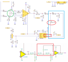
    I noticed that the circuit has C27 connected to the output of TSZ1221ST op amp. Is this a typo? What is actual circuit configured on the tested PCB?

    If you remove R131 or 150kΩ resistor, what does the Vout do? At the moment, I am only interested to voltage measurement at Vout or Vp as shown in the schematic below. 

    What is the INA823's application? 

    The 4.7uF capacitor in the differential input filter is a bit large, I would reduce it and increase the line input impedance somewhat. As is, the differential mode LPF is operated at approx. 3.3Hz and common mode LPF has BW is approx. 31.2kHz. Typically, I would keep the LPFs a decade apart or so, see the attached application note below. 

    https://www.ti.com/lit/ug/sbou115c/sbou115c.pdf?ts=1700211533559

    The 3rd question is about the application's input. What is the input signal level? How is the input configured? What is common mode voltage level?

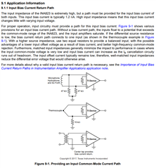
    If the input sensor is floating type, I would add the input bias current return path. I need to know what types of sensors are used and configured at the INA823's input. It is possible that the large differential 4.7uf capacitor takes a long time to charge up due to the weak input signal level.  

    Enclosed is the INA823 circuit transfer from your image. Please consider this as an example for now. 

    INA823 Slow Warmup 11172023.TSC

    If you have other questions, please let me know. 

    Best,

    Raymond

  • Hi Marek-san and Raymond-san,
    Thank you for your schematic advice.

    The customer input is a Resistive-Bridge Pressure Sensor.
    I have given your advice back to the customer.
    I will give you feedback once I receive a reply from the customer.
    INA823 23110700_2-2-circuit diagram.xlsx
    Best regards,
    Hiroaki Yuyama

  • Hi Hiroaki,

    Sounds good. We'll wait for your customer's feedback.

  • It's been two weeks since last reply.  Thus, I'll close this thread for now.  If you need further assistance, please reply or start a new inquiry.