Other Parts Discussed in Thread: OPA596,
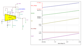
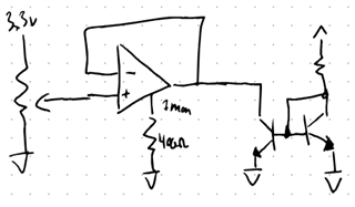
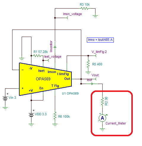
I’m driving a laser diode with this opamp (single supply) and monitoring it using the Imonitor pin with a 400ohm pull-down to ground.
I’m aiming for a 95mA output which requires just over 3V with my specific laser and associated series resistors. I’m powering the opamp off 3.3V.
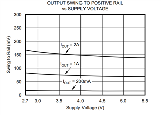
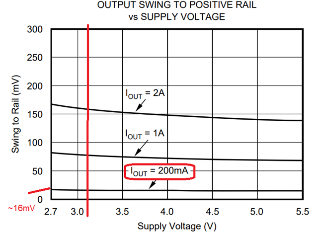
This isn’t a problem for the output swing since the data sheet indicates a swing to within ~25mV of the positive power rail.
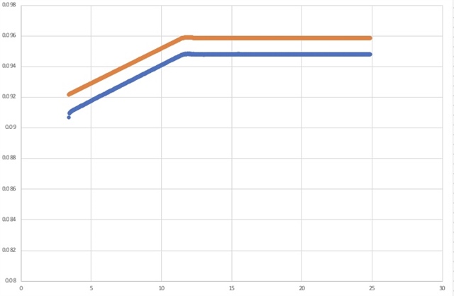
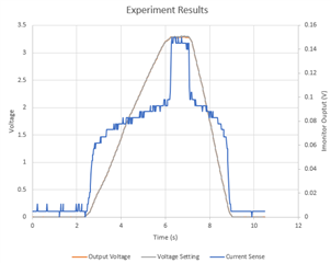
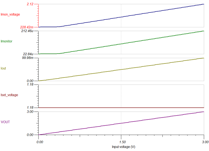
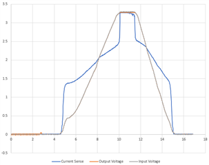
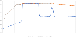
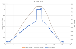
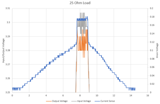
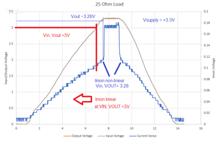
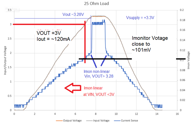
The issue is with the Imonitor pin. As the output voltage approaches 3V, there is no longer a linear relationship between Imonitor’s output and the actual output current. 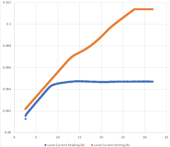
In this plot “laser current reading” is current measured by another device. “Laser current setting” is the current as reported by IMonitor. Both converted to amperes with the appropriate math. I assume the small offset at the start is due to component tolerances.
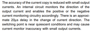
Is there any documentation on nonlinearity of the Imonitor pin with output voltages approaching the power rails? The only plots I found were regarding output current or temperature.


