This thread has been locked.

If you have a related question, please click the "Ask a related question" button in the top right corner. The newly created question will be automatically linked to this question.

LMP7721: Output drift

Part Number: LMP7721

Hi

I am using the LMP7721 as the input stage to a circuit used to measure electrostatic charge.

The amplifier is configured such that the Voltage Supply rails are +/- 2.5V

The remaining connections are thus;
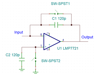
Theory of operation is the switches across the capacitors C1 and C2 close to discharge any residual charge and then opened ready to measure the charge applied to a sense plate connected

to the input. The magnitude of the charge applied equates to a maximum Voltage across the capacitor C1 of approximately 0.8V. However, before any charge is applied the output begins to drift.

The magnitude of the drift is significant - up to 2.1V over a 30s period.

I have used the circuit configuration before but the original amplifier (OPA128 - selected because of it's very high input impedance) is now obsolete.

I selected the LMP7721 because of the very high input impedance and extremely low input bias current, but the drift is a major issue.

Can you assist with this please...?

If the LMP7721 was a poor choice, could you offer a suitable alternative..?

Thanks

  • Ken,

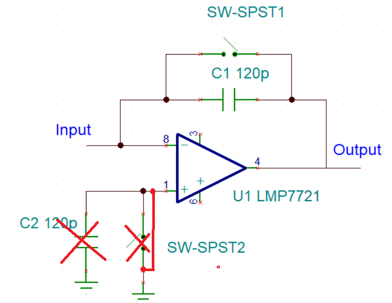
    First, in order to eliminate the offset voltage shift caused by the internal input bias current (IB) in the integrator circuit, you must ground the non-inverting input - see below.

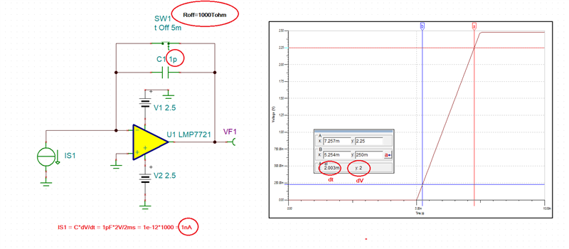
    Knowing what input current level you expect to measure, you must pick appropriate size feedback capacitor based on Ic = C*dV/dt equation.

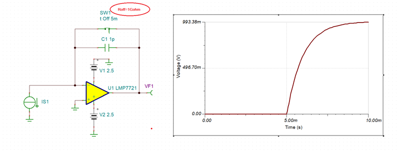
    Keep in mind that the time constant, Tconst = C1*Roff must be much longer than dt time you expect for a given current level OR your measure will be in error - see below (Tconst=1pF*1Gohm = 1ms). 

    LMP7721 integrator.TSC

  • Marek

    Shorting the non-inverting input to ground makes little difference to the difference problem I am seeing.

    The response time to the applied charge is not the issue. It is more the way the output drifts with time with no input connected.

    The idea of the second capacitor on the non-inverting input is to cancel the effect of input bias current once the measurement begins.

    Something else seems to be causing the drift.

    Many thanks for your assistance.

    Ken

  • With no input connected, there are still input bias and leakage currents present that will cause output to drift. Based on the numbers you previously provided the total current may be back calculated to be: Ic = C*dV/dt =  120pF*2.1V/30sec = 8.4pA; if the measurement is done at room temperature, the most likely reason for the current is the moisture, lack of shield/guards, or other contamination left on the PCB after it was assembled.

    Please read the article below to learn about the challenges involved in sub-picoamp applications:

    http://www.edn.com/design/analog/4368681/Design-femtoampere-circuits-with-low-leakage-part-one

  • Marek

    Many thanks for the information and support. I believe that the problem was with one of the reed relays in the circuit. Replacing the part appears to have solved the problem of drift.