This thread has been locked.

If you have a related question, please click the "Ask a related question" button in the top right corner. The newly created question will be automatically linked to this question.

AMC3301: Unexpected behavior from PSpice simulation

Part Number: AMC3301

Hello,

My customer has run simulations using PSpice for TI, but it didn't work as expected.  Would you please tell me what they should do for getting expected results?

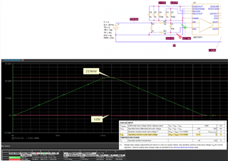
They referred to the Figure 8-1 on page 27 in the datasheet and made the circuit shown below.

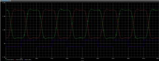
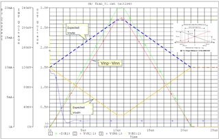
Then they ran PSpice for TI simulations, but it didn't give the expected behavior as shown below.  Would you please tell me what they should do for schematic or simulation conditions?
Best Regards,

Yoshikazu Kawasaki

  • Hi Kawasaki-san,

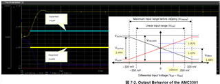
    It looks like fail-safe output is occurring, perhaps due to the input voltage range being outside of the common-mode input voltage limits. 

    I suggest testing with a simpler input voltage such as DC or sinusoidal before using the current source to confirm operation. 

  • Hello Alex-san,

    Thank you very much for your advice.  They did DC input, but it didn't seem to work correctly.  Would you please check the schematic, simulation result and give me your comments again?

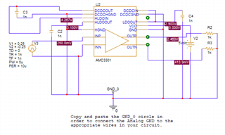
    - DC input schematic

    - Result

    - CM voltage check

    Best Regards,

    Yoshikazu Kawasaki

  • Hi Kawasaki-san,

    I do not see from the attached what the error may be. Please see my attachment that I am able to simulate correctly. 

    AMC3301_PSPICE_TI_Test.zip

  • Hello Alex-san,

    I'm asking them to use the same conditions as you and check if they can reproduce the same results you gave this time, but before getting their simulation result, would you please let me confirm if you use the same spice mode files shown below?

    www.ti.com/.../sbam474 

    The conditions you used are a little bit different from theirs, but do you think you can use the same conditions to check if you really can't reproduce their results?  I'm afraid I'm not familiar with PSpice simulation and don't have enough time to learn how to do it.

    Best Regards,

    Yoshikazu Kawasaki

  • Hello Alex-san,

    My customer has run simulations using the files you sent and confirmed they could reproduce your simulation results.  They also could get expected results if they modified the Tr,Tf,PW from the ones you used.  However if they use their original schematic, they still get the unexpected results.  Can they fix the issue if they use the spice model which can be downloaded from the following site?  If so, would you please tell me how to update their model?

    https://www.ti.com/lit/zip/sbam474

    I sent you friendship request so that I can send you the files that my customer has been using in case if you need those, so please accept it.

    Best Regards,

    Yoshikazu Kawasaki

  • Hi Kawasaki-san,

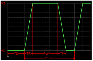
    I don't think this is a model issue but a current source parameter issue. I think the TR and TF are much too long, 10uS in their simulation compared to the Pulse Width of 1uS. 

    V1 = First Voltage

    V2 = Second Voltage

    TD = Initial Delay

    TR = Absolute Rise Time

    TF = Absolute Fall Time

    PW = Pulse Width

    PER = Period

  • Hello Alex-san,

    Thank you for your comments again.

    They should know the meaning of the parameters, but I'll check it.  I'm not sure why they can't use such long Tr/Tf even though you suggested to use DC input first.  Would you please tell me about it?  If they need such input, do you mean PSpice can't support that since AMC3301 should be able to handle that?

    Do you think you can make the same schematic as them and check if you also have the same unexpected output?  If you can accept my friendship request, I can send you the files they use so that you can run simulation easily.

    Best Regards,

    Yoshikazu Kawasaki

  • Hello Alex-san,

    I asked if their system will have such slow rise/fall time input, but they just used that to check the output of AMC3301, so it's not system requirement.  The reason why they configured the narrow pulse width is to minimize the simulation time.  The files you sent me yesterday were modified to their conditions(Tr=Tf=10us, PW=1us) and confirmed working well, so they think simulation environment should have caused the different results.  Would you please tell me why they didn't have issues if they used your files, but they did if they used their files?

    Best Regards,

    Yoshikazu Kawasaki
  • Hi Kawasaki-san,

    I have accepted your friend request. I'm not sure why their simulation is having an issue. PSPICE can be difficult to use and diagnose. Perhaps the simulation profile is setup incorrectly. 

  • Hello Alex-san,

    Thank you for accepting my friendship request.  I sent you the files my customer used.

    Best Regards,

    Yoshikazu Kawasaki