This thread has been locked.

If you have a related question, please click the "Ask a related question" button in the top right corner. The newly created question will be automatically linked to this question.

INA240: Question on Impedance of output pin to GND

Part Number: INA240

Dear TI Experts and Guru,

  We have a single malfunctioned INA240 with a configuration of GND reference output, and would like to check how it was damaged. 

For a normal device when powered, the impedance between output pin and GND  is about 0ohm measured by DMM. When our differential input is about 0.6mV, our output voltage is about 33mV.

For the malfunctioned device,  the impedance between output pin and GND  is about 40ohm measured by DMM. Whatever its input is, Its output voltage is fixed at -0.4mV.

When not powered, the impedance between output and GND of both cases are the same, about 370kohm.

Hope you can shed some light on how to anaylze this problem. And bty, how shall we understand that the impedance between output and GND is about 0ohm for the normal case?

Thanks,

Yuanchen

  • Hello Valued Engineer,

    I'm sorry to hear about this.

    I am not sure this is an output pin issue. There could be damage to one of the input pins. Try measuring the resistance to ground at IN+ and IN- pins (with respect to device GND pin) and compare between normal and malfunctioning device. If possible, you may want to disconnect the shunt resistor or remove the INA240's from the PCB to get a better resistance measurement, but I recommend the following steps first:

    1. Please provide a schematic.

    2. Try to measure input currents (input bias at IN+ and IN- pins) and also measure supply current into VS pin. You could try breaking these traces open and inserting a 10Ω to 100Ω in-series with the pins and measure the voltage drop to get a decent measurement of these input currents.

    Sincerely,

    Peter

  • Hello Peter,

    Thanks for your reply.

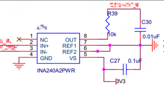
    Please see our related circuit as follow:

    Having measured when powered-on the impedance to GND at IN+ and IN- of malfucntioned INA 240 are both 0ohm or so, so are the case for normal INA240 circuit.

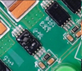
    And this malfunction device was found after a heat aging test without power-on (less than 60 degree C) for a few days and has some melting traces on the case, before the test the circuit behavior and the component case was normal. We have four IN240 in a single board, and only one of them happened to be like this. We believe this was a small probability event.

    Based on the fact that we only have a malfunction INA240 component as such as far, what we actcually aim for here is simply a reasonble analysis for possible cause of the damage, or how shall we carry out any right failure analysis as you experts would recommend.

    We haven't finished for the current you recommend to measure. so far we have used an Infrared thermometer to check that there was apparently no extra heat from this abnormal INA240 component, compared to other normal IN240 nearby. Shall we ask first if the supply current is abnormal compared to normal case of INA240, what conclusion can we get to? And if it is exactly (or about) the same, then what shall we do for next?

    Lastly, any more advice on any precaution we shall take for the circuit?

    Thanks.

    Yuanchen

  • Hey Yuanchen,

    What are the powered-on IN+ and IN- resistances to ground for normal working device? When measuring these resistances, you really want to make sure the device is removed from PCB because you may be measuring another board resistance in parallel.

    0-Ohm input resistances to ground are not what the device should be showing. If this value remains when input pins are disconnected from PCB,  then this would indicate a short to ground inside the device, most likely a short in the device ESD cell.

    What traces were melted. This certainly seems like it should be investigated.

    Other than this, please try to measuring IN+ and IN- input bias currents (IB+ and IB- respectively) when the PCB is powered on and/or lift up the IN+ and IN- input pins from the PCB pads and measure input resistance.

    After this, try measuring the supply current.

    An internal short from damage inside device does not have to sink significant current to generate noticeable heat.

    Measuring these input current will help us indicate where the damage could be.

    Sincerely,

    Peter

  • Hello Yuanchen,

    Since have not heard back from you, I will mark this thread as resolved; however, if the issue is not resolved, please post right back here so we can continue the investigation.

    Sincerely,

    Peter