This thread has been locked.

If you have a related question, please click the "Ask a related question" button in the top right corner. The newly created question will be automatically linked to this question.

INA214-Q1: REF pin high impedance will impact output have noise or not stable

Part Number: INA214-Q1

Hi expert,

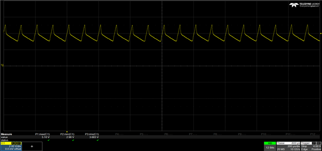
My customer find some issue about Ref pin floating or give it a 3.5kohm will see the output signal have 10khz abnormal noise as this pic

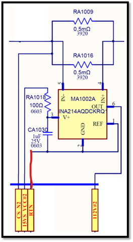
their original circuit connect is Ref pin and Gnd pin connect together then connect to RTN (system Gnd), but REF pin and Gnd pin open (did not connect RTN) will see output like pic.

so they have two question as bleow

Q1.why output will see like this ?

Q2.output pin has this noise cause from REF pin or Gnd pin or both will impact ?

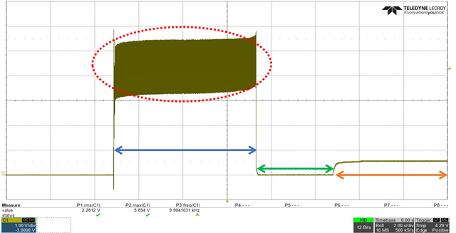
Then they try to use the auto resistor connect between GND/REF to RTN before power up and they give 3 section by different resistor value.

blue one is 3.5kohm

green one is <1ohm

orange one is 10kohm

and they have 2 question about this result

Q3. Why section 3(orange) is also high impedance and output result can not see like section1(Blue)  

Q4.Before power up GND/REF pin to RTN status will impact output pin performance and why the root cause ? (because section 3 also high impedance but not any risk on output) 

Please help on comment these 4quesion. THanks!

Eddie

  • Chao Fu,

    Thanks for the question and using the E2E forum.

    We're looking into this and will give you an update when we return from the holiday weekend.

    Louis

  • The GND pin must always be connected. Leaving it unconnected makes the ground current flow through the ESD clamping diodes of the I/O pins, which violates the absolute maximum ratings and might damage the device.

    The resistors inside the INA214-Q1 are precisely calibrated. But if the REF pin is floating or connected to an external resistor, the effective resistance between the positive input and the reference voltage does no longer match the negative feedback resistor, and the output voltage is affected by the common-mode voltage, and can easily pick up noise.

    The strange waveforms you're seeing are to be expected when the GND/REF pins are not connected correctly. The only way to prevent these problems is to connect the GND/REF pins.

  • Hi Ladisch,

    As you mentioned REF pin have to connect to gnd to make sure low impedance.

    But why my customer do the test to simulation 3 section to let REF impedance from high low high.

    Just power up beginning section 1 3.5kohm will see very obvious noise on output , but section 3(orange) up to 10kohm will not see to much noise ?

    That's my customer question3 why power up beginning high impedance on REF pin will see the noise , but power on later turn up high impedance(section 3 orange) on REF pin will not see like section 1(Blue) ? 


    Eddie

  • Hi Eddie,

    The device ground pin and bypass cap should be connected to system ground directly, not through a resistor. If this is the case, a resistor between REF pin and GND will not cause the noise, even though such resistors will cause DC output error and should be avoided.  

    Regards, Guang