Other Parts Discussed in Thread: OPA381, TINA-TI, OPA392
Hello community,
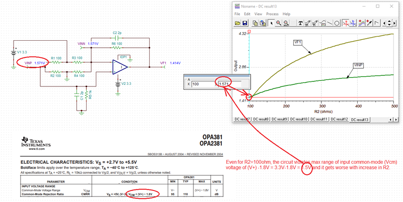
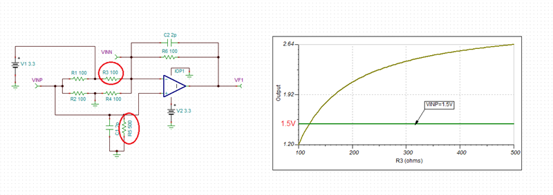
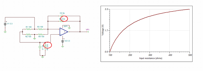
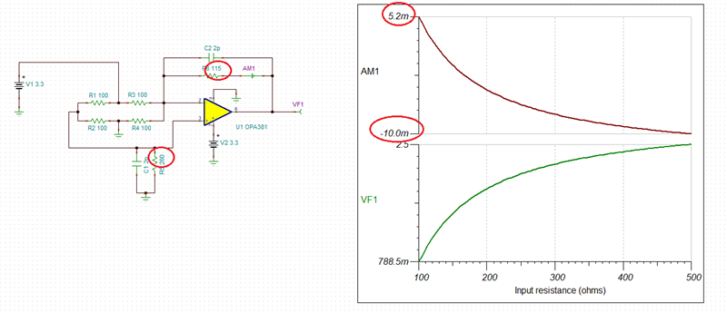
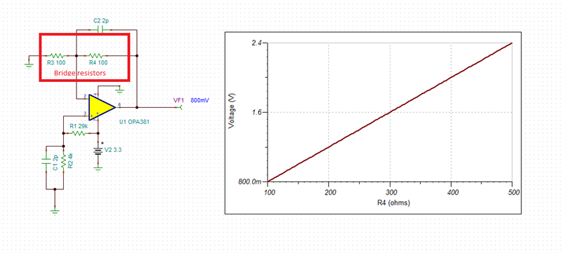
I have designed a strain gauge sensor using OPA381 in a bridge configuration in TINA-TI (attached herewith), taking reference from the application circuit of MAX4239.
When I simulated the schematic, I found that the circuit is working correctly and very precisely for the minute change in resistance of R2, but it does not meet my requirement for the following reasons:
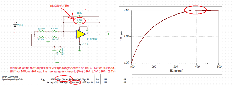
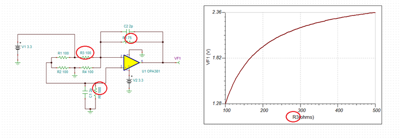
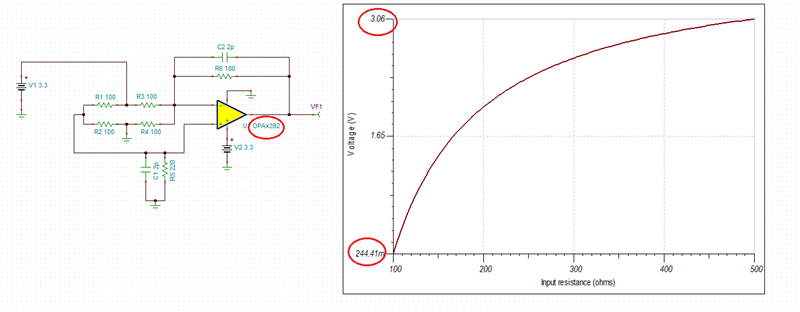
1. My sensor has a very high gauge factor (typically between 5 and 10). Since I need a linear change in voltage with a change in resistance (for example, if the base resistance is 100 ohms, I am expecting a linear voltage change when it reaches to 500 Ohms or so). But typically in the above circuit, in bridge configuration, the voltage saturates within a small range of resistance change (around 110 in above example). Any explanations and ideas to tune these values or modifications!
2. I am wondering why the maximum voltage output is only 1.65 V and it saturates for higher values of resistance.
Thank you for your kind consideration.
Best regards,


