Other Parts Discussed in Thread: OPA310
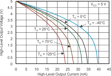
A few years back, we switched from TLV274CPW to TLV274IPW (industrial varsion). The circuit I have the opamp tied to is a reference signal or 4vdc (from an A/D). The op-amp is in a unitiy gain configuration. I use the 4v reference to power up some resistor pots. The total current output for all 4 drivers is 40ma. The output is of course 4vdc. The chip is powered with 5vdc +/-0.5vdc.
When circuit is running the normal current is 24ma. When I push two resistor sensor buttons, the current draw goes up to 40ma. When I was using the TLV274CPW, the voltage out of the opamp is 4 volts (which is what it is supposed to be). When I pushed the two resistor buttons to add the extra load, the voltage remained the same (which is good).
The issue I had was with the TLV274IPW (industrial device). At normal resting state (24ma), the voltage still read 4vdc. When I added the extra load though (16ma added which is equal to 40ma), the voltage dropped by 150mv. I don't think that is normal. According to the datasheet, it should be able to supply 100ma max. Has something changed?


