This thread has been locked.

If you have a related question, please click the "Ask a related question" button in the top right corner. The newly created question will be automatically linked to this question.

THS4551: Power Supply Decoupling

Part Number: THS4551
Other Parts Discussed in Thread: LMH34400

In the datasheet in section 8.7 (Terminology and Application Assumptions) it states:

"Good power-supply decoupling is required. Often a larger capacitor (2.2 µF, typical) is used along with a high-frequency, 0.1-µF supply decoupling capacitor at the device supply pins (share this capacitor with the four supply pins in the RGT package). For single-supply operation, only the positive supply has these capacitors. Where a split supply is used, connect these capacitors to ground on both sides with the larger capacitor placed some distance from the package and shared among multiple channels of the THS4551, if used. A separate 0.1-µF capacitor must be provided to each device at the device power pins. With cascaded or multiple parallel channels, including ferrite beads from the larger capacitor to the local high-frequency decoupling capacitor is often useful."

The above is not useful and the author appears to be ignorant of capacitor technology that's been commonly available years before the datasheet (dated 2022). A 2.2uF X7R in an 0603 package _is_ a good high frequency decoupling capacitor. Paralleling it with an 0.1uF X7R capacitor would create a huge spike in impedance, caused by the parasitic L of the 2.2uF resonates with the C of the 0.1uF. To damp this down a resistor in series with the 2.2uF could be used or a capacitor with an inherently higher ESR than X7R caps, such as a tantalum or aluminium electrolytic. The last sentence stating that ferrite beads are often "useful" does not explain what problem with the THS4551 they solve or which ferrite bead(s) to use. I would guess is it coupling from one amplifier to another through the supply rails, which is much more predictably dealt with by using series resistors of a few ohms rather than ferrite beads.

Here is what I think is a more rational and useful way to determine the amount of decoupling required for the amplifier:

1) If the bandwidth of the input signal is BW Hz then, to a first order approximation, the variation in the supply current of the amplifier will also have a bandwidth of BW Hz.

2) For a signal superimposed on the supply then the amount of that signal at the output of the amplifier is equal to the PSRR of the amplifier at the frequency of the superimposed signal multiplied by the gain of the amplifier.

3) The amplitude of the variation of the supply current is equal to the output voltage swing divided by the load resistance, with the (unachievable) worst case for a RRO amplifier being the supply voltage divided by the load resistance.

Let's put some number in and see what comes out.

Vcc = 3V; Vee = 0V; Rload = 100-ohm; BW = DC to 20MHz; Gain = 0dB

The PSRR+ for the THS4551 is falling at -6dB/octave from ~85dB @ 5MHz, so at 20MHz the PSRR would be ~73dB. With gain = 0dB, the gain from Vcc to the output is (0 - 65) = -73dB

The maximum variation in supply current  Vcc / Rload = 3V / 100-ohm = 30mA.

With a single 2.2uF X7R 0603 used for decoupling for each THS4551:

Impedance at 20MHz is limited by the capacitor + mounting inductance. Assuming a total of 2nH the impedance is ~0.25-ohm. With the 30mA supply variation this would induce a ripple voltage on the supply of 7.5mV. At the output this would introduce a ripple of ~1.7uVpp in a 6Vpp output, or -131dB lower than the output signal.

At 10kHz the impedance of the 2.2uF is ~7-ohms, so the ripple voltage would increase to 210mV. However, at 10kHz the PSRR improves to 105dB. At the output this would introduce a ripple of ~1.2uVpp in a 6Vpp output, or -134dB lower than the output signal. In reality at 10kHz and lower frequencies other "bulk" capacitors on the board and the output impedance of the voltage regulator would push the impedance well below 7-ohms, leading to even lower voltage ripple.

If isolation between amplifiers is needed then using, for example, a 2.2-ohm resistor in the power supply to each amplifier would form an RC low pass filter with the 2.2uF decoupling capacitor for each THS4551 with a -3dB frequency of ~33kHz. The peak to peak output swing, even into 100-ohm load, would be reduced by less than 150mV. Using a resistor avoids LC resonance that can be caused by using ferrite beads and the effect of changing values is predictable.

In summary:

Ignore the datasheet's advice on decoupling and do your own analysis. If you can't be bothered to do an analysis then a 2.2uF 0603 X7R per THS4551, possibly with a series resistor of a few ohms if isolation between amplifiers is required, should be good enough for the following applications:

  • Gain close to 1 driving a heavy load (100-ohm) with large output swing. E.g., ADC driver.
  • Gain much larger than 1 driving a light load (> 1k-ohm) with large output swing or a heavy load with small output swing.

Hopefully this will be of help to someone and might inspire the engineers who produce the datasheets at TI to up their game and not just paste boilerplate "advice" for decoupling circa. 1990 ;-)

  • Hi Robert, 

    For high speed amplifiers the power supply capacitors are not selected based on the input signal frequency, but based on the loop gain of the amplifier to ensure stability. In your example of a 20 MHz signal using the THS4551, the signal bandwidth may only be 20 MHz but the loop gain bandwidth of the amplifier is going to be ~150MHz.

    In order for the amplifier to remain stable the phase delay from the input through the amplifier and back to the input from the feedback network must be less than 180 degrees. If the amplifier's power supply connection appears to be a high impedance at these frequencies then the amp will not have the appropriate supply current it demands at these frequencies.  A limit in the supply current frequency will cause a "slow down" or phase delay in the amplifier which will delay the total loop gain phase and cause instabilities. 

    Additionally we must account for unknown parasitic impedances in the power supply traces that connect the capacitors to the amplifier. Trace impedance coupled with the capacitors own impedance can all contribute to adding additional high frequency isolation between the capacitor and amplifier. This is why you often see that high frequency devices will have local smaller capacitors places very close to the devices pins to provide the high frequency current and then also larger "bulk" decoupling capacitor located further away that provide the main power supply current. On some devices we even suggest using wide package capacitors such as 0306 as they are particularly low impedance. 

    Regarding ferrite beads, they are simply used on the bulk supply connection to eliminate any noise on the power supply connection coming into the board. 

    Of course, we are unable to predict all use cases, board layouts, and parasitics that specific applications may introduce, which is why we just provide general suggestions for supply capacitors that are high performance enough to try and account for these unknowns. 

    Best regards, 

    Jacob 

  • Hi Jacob,

    Thanks for the reply.

    Above 100MHz all but the most specialised chip capacitors are going to look like inductors based on their package size and aspect ratio; capacitance beyond 100MHz becomes pretty much immaterial as they all look like the same value inductor! Once the inductances of the capacitor, via, trace and IC lead frame are taken into account virtually any external capacitance looks look like an inductor to the circuitry in an IC at 150MHz. At 150MHz a 0402 0.1uF will look exactly the same as an 0402 2.2uF as far as the IC is concerned. Below 1MHz the 2.2uF has 20 times lower impedance than the 0.1uF. I therefore think the analysis based on PSRR, load and signal frequency is more appropriate to select the value of decoupling capacitance than loop stability, which is only going to set a bare minimum.

    The VSSOP package size of the THS4551 would make a 0603 capacitor a reasonable choice. A 0603 2.2uF has a much better capacitance vs DC bias characteristic than 0402 2.2uF capacitors (particularly if running on a single rail of +5V), hence my recommendation for that value in that case size. Lower operating voltages and/or a smaller IC package size would probably make 0402 sized capacitors more appropriate.

    My point being that for an amplifier such as the THS4551, once the inductance of the decoupling capacitor plus its connections to the IC is low enough to keep the IC stable, reasonable advice for the value of the capacitor is as large as the user can get or afford in the capacitor package size chosen, rather than use 0.1uF + other larger value(s) that is so often parroted on application notes and datasheets. The THS4551's datasheet, rather than advising 0.1uF + 2.2uF (which if both ceramic would cause a peak in the impedance around 11MHz) it could more usefully say:

    "Use a ceramic 0402 or 0603 decoupling capacitor for each power rail. Place each decoupling capacitor close to the IC pin it is decoupling and minimise the inductance of the connections between the capacitor, IC and ground plane as much as possible. The value should be at least XnF for loop stability and based on the connected load, PSRR and bandwidth of the signal."

    Advice on how to minimise the inductance of the connections and avoiding or damping parallel resonance of different value capacitors connected in parallel would be useful too. If that's too much to put in a datasheet then a brief summary combined with a link to an application note with more detail could be provided.

    Someone at TI may want to update the THS4551 datasheet with respect to the use of ferrite beads because it is telling users it might be "useful" to put them just before the high frequency decoupling capacitors, not as board entry filter components as you have just stated. If the former has been found to be "useful" then at least tell users what ferrite beads were "useful" and what the benefit was, as putting inductors in power leads only makes the job of the decoupling capacitors harder!

    Regards,

    Robert

  • Hi Robert, 

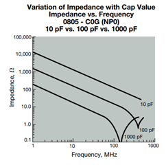
    Thanks for the further feedback. For smaller sized COG style ceramic capacitors, they actually hold up fairly well across frequency which is why we suggest them in parallel with the larger caps. Below is an image from an AVX document where they measured the impedance of 0805 size caps at different frequencies. As you can see the 0.1nF doesn't go inductive until ~400 MHz compared to about 120 MHz for the 1nF cap. 

    Of course specialized low impedance capacitors like 0306 packages exist for even better performance. You can see an example of that on our LMH34400 transimpedance amplifier EVM. That part is particularly sensitive to power supply decoupling so we needed to use the highest performance devices. 

    Also beyond stability, keeping a good high frequency supply connection helps to maintain linearity performance by not degrading the loop gain of the circuit prematurely. I can speak from experience of using some boards with poor supply decoupling that will significantly degrade harmonic distortion. 

    I will make a note to check on the language used in the datasheet on minimizing inductance of connections. Typically that is one of the points we try and include in all our datasheets, but it may have been missed or not clarified in the THS4551 in particular. 

    Regards, 

    Jacob 

  • Hi Jacob,

    A 10pF 0805 looks capacitive to even higher frequencies, though you might need a few to provide any significant decoupling! 400MHz / sqrt(1nF / 0.1nF) = 126MHz. I.e. the 0805 capacitors have virtually the same inductance (~1.6nH), but the series resonant frequencies of the those with smaller capacitances are higher. Outside the narrow series resonant nulls, the 1nF capacitor has ten times lower (<200MHz) or the same (>500MHz) impedance than the 100pF. Given a choice, two 1nF capacitors would give the same or better decoupling (i.e. lower impedance) over almost all frequencies compared to 100pF + 1nF.

    If reasonably accurate models of the capacitors, interconnect and PCB plane capacitance are available then SPICE simulations can be used to pick a range of capacitor values that achieve a particular impedance profile over a given frequency range. This generally requires the values of most of the capacitors to be spaced by no more than a factor of 2 or 3 to avoid large parallel resonance spikes in the impedance, particularly at the higher frequency end on boards with substantial plane capacitance where it resonates in the mid 100's of MHz range with the ESL of the chip capacitors. I can see from the LM34400 EVM schematic that the spacing of the capacitor values does indeed mostly follow a factor of ~2 to keep the magnitude of the parallel resonant spikes in check.

    This has been an interesting discussion and hopefully people searching for information on decoupling will come across it and at least think about what they are trying to achieve rather than just stick 100nF + 10uF capacitors on the power rail(s). It would be great if IC manufactures would publish better advice about decoupling, either in device datasheets, general application notes or training videos to illuminate this much ignored and often perceived as black magic area of electronic design.

    Regards,

    Robert