This thread has been locked.

If you have a related question, please click the "Ask a related question" button in the top right corner. The newly created question will be automatically linked to this question.

THS3095: 1PPS [0-10V] 50 ohms Driver

Part Number: THS3095
Other Parts Discussed in Thread: THS3491, UCC27537, TINA-TI

Hello,

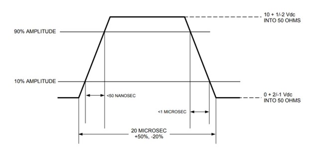
I need to design a 1PPS driver with rising edges <50ns and driving a 10V voltage through a 50ohms adapter (the total supply is therefore 20V due to the bridge divider).
I found that the THS3095 component could drive a 50-ohm line. However, the current required for the voltage level is 200mA. This component doesn't seem to be able to supply this current.

Is there an amplifier that can achieve these specs?

Thanks in advance,

Best Regards,

Louis

  • Look at the THS3491

  • I can't simulate the PSpice model on LT Spice. Could this be due to the simulation model?
    I have another question: can the THS3491 work as a non-linear comparator?
    Best regards

  • Hello Louis,

    For which device are you having SPICE simulation issues?

    When designing with the THS3491 and other current-feedback amplifiers, please consider checking the differences between voltage-feedback and current-feedback architectures.

    If you are able to share your design needs or current circuit for your comparator, I could assist with a review or discussion on theory.  Depending on your familiarity with current-feedback devices, there are some common challenges or issues which can be tricky.

    Best,

    Alec

  • If you want to output a digital signal, then the simplest solution would be a gate driver like the UCC27537.

  • Here is the error code :

  • I changed the emission coefficient to 0.1 (".model D_IN_CLMP d is=1e-014 n=0.02 rs=1) and the simulation works. Is it a problem for the model to change this coefficient?

  • Thanks for the suggestion, I'll look into it

  • Hello Louis,

    TI's models are designed for use in Pspice and TINA-TI (the simulators we use at TI), but are not necessarily released to be 'drop-in' models for LTspice.  As LTspice is software originally produced by Linear Technologies, we are not able to debug or advise using TI models in LTspice. 

    However, we are able to support sharing a resource which could assist with using TI models in generic spice software, whether it be Pspice or not.  A colleague and I provided support in a prior thread: 

    https://e2e.ti.com/support/amplifiers-group/amplifiers/f/amplifiers-forum/1258721/lmh6401-lmh6401-simulation-on-ltspice

    In general I always recommend using either PSPICE for TI or TINA-TI for simulating TI models.  Both of these software programs are used in development of the SPICE models and are known to work with TI designs.

    PSPICE for TI already has updated TI models present in the library, and has documentation and guides to help you get started. 

    If you change a TI model's source code, TI is no longer able to represent or warranty the model as a technical representation of a TI device.  I caution against editing SPICE models if you are not very familiar with how SPICE modeling is accomplished, as minor changes can create convergence issues or misrepresent performance.

    Regarding your application, I cannot yet tell if you need a digital TTL logic levels at the output, or if you require amplification and comparison of analog signals.

    Best,

    Alec 

  • Ok thank you for this information. I was able to simulate the model with PSpice and it works well. But, I find a phenomenon that I can't explain. The amp's output starts to increase in the absence of input voltage.

    Do you have any idea why?
    I've attached the simulation project if you need it.1PPS.zip

  • Hello Louis,

    Thank you for sharing your source files for PSPICE; I will take a look at your circuit and simulation.  I agree the observed behavior is not as expected.

    Best,

    Alec

  • Hello Louis,

    I ran a simulation in PSPICE and was able to replicate your behavior.  I did also run the same simulation with the same THS3491 model in TINA-TI; the results do not show the ~943mV drift you are seeing at ~48us.  Instead the TINA-TI simulation shows the expected behavior of both the input pulse and output signal reaching a zero-volt steady-state.

    It is apparent this difference in behavior is not due to the model, which is constant.  Rather, this difference is between simulators, and is curious.  There is likely a boundary condition setting or a simulation parameter in either piece of simulation software which either creates or avoids this signal artifact we observed.  I am sharing a screenshot of the TINA-TI circuit below:

    The signal levels are 12.8V for the green output signal & 3.3V for the red input pulse.

    tina_ths3491_no_offset.TSC

    Best,

    Alec

  • Hello, Thanks for this informations.

    I changed the amp supply voltages to -10V for VEE and +20V for VCC. After that, I no longer have the offset problem. I'm afraid it's a saturation problem and not an artifact. However, the 0V voltage is quite far from the supply rail voltage for -5V. Do you have any ideas/suggestions about saturation voltages and supply rails?

    Best Regards,

    Louis

  • I've just simulated the assembly on TINA-TI. Indeed, the ~943mV drift no longer appears. On the other hand, I've tested the assembly in saturation, and I'm having trouble understanding the negative saturation that occurs here at 9.78V. 0880.tina_ths3491_no_offset.TSC

  • Hello Louis,

    I am seeing similar behavior in my simulations; when I push the THS3491 into saturation on PSPICE the resulting output signal is set at mid-supply, ~10V.  

    The datasheet suggests an input signal headroom of 4.1-4.3V, which is being observed by your circuit.  The output swing limitation is also followed, which requires 1.5V to either supply.

    For the TINA-TI results when THS3491 is pushed to saturation, perhaps the observed signal showcases an issue with negative supply headroom when using asymmetrical supplies.

    When using symmetrical +/-15V supplies with a zero DC offset 7V amplitude 1MHz sine wave, the results are closer to what you would expect:

    When using the asymmetrical supplies of -5V and 25V, the headroom for output swing is closer to 2V or 2.1V, which is where you see the 9.78V signal jump occur in the output swing you shared above.

    By using asymmetrical split supplies, for the THS3491, you are encountering a shift in the allowable headroom.  Operating unbalanced supplies would appear to increase the headroom required to operate the THS3491.  This headroom increase of ~300-500mV is enough to cause the behavior we are observing.

    Regarding your shift to -10V and 20V supplies for the 3.3V pulse signal, I ran a simulation at those supplies to check your observations.  I do find the offset drift to 943mV does not occur at the -10V and 20V unbalanced supplies.

    To investigate, I set the supplies back to -5V and 25V but set the input pulse to range from 1V to 4.3V, effectively adding a DC bias to the pulse signal.  When I used this method, I saw no 943mV signal even though I was using the original unbalanced -5V and 25V supplies.  

    Next I tried a 0.5V to 3.8V signal, which also avoided any output drifting after the pulse.  I believe the behavior observed with the 0V to 3.3V pulse is being affected by input signal headroom limitations due to unbalanced (asymmetrical) split supply.  However, I believe the issue observed when using a sinusoidal signal is due to a shift in output signal headroom.

    If you could share the signal details you wish to use for your system, I can help simulate and dial-in the THS3491 design to suit your application.  

    I am not sure what type of signal will be used in application, vs. using pulses or sine waves for testing and headroom investigation.

    Best,

    Alec

  • Hello,

    Thank you very much for your detailed reply. More concretely, the signal I need to produce is 0V - 10V matched 50 ohms -> So at no load, the voltage must be around 20V to get the 10V following the 50 ohm divider bridge. The time constraints are mainly on the rising edge (<50ns between 10% and 90% of the signal).

  • Hello Louis,

    Thank you for your description of circuit needs.  I will work with simulation and provide my response to address your design needs.

    Best,

    Alec

  • Hello Louis,

    Operating your THS3491 circuit with a larger load (1kOhms) results in no output drift up to 943mV, even with 50ns rise & fall times on the signal.

    When a 50 Ohm load is present instead of 100 Ohm load, the offset increases.  I am going to work on seeing how to stabilize the output of the amplifier after the pulse is done.

    Is the pulse a singular pulse or part of a periodic signal or pulse train?

    Please also see this prior thread on loading and impedance matching with THS3491:

    e2e.ti.com/.../ths3491-impedance-matching-to-drive-a-50-ohm-transmission-line

    Best,

    Alec

  • Hello,

    Thanks for your feedback. The pulse is a periodic signal with a period of 1 second. I hope that clears things up for you. Don't hesitate to let me know if you have any research leads in relation to output stabilization.

    Best Regards,

    Louis

  • Hello Louis,

    Thank you for sharing the signal periodicity.  I am running simulations to find a good and operable circuit configuration for your application.

    Best,

    Alec

  • Hello,

    Ok thanks for your help

  • Hello Louis,

    I am still working on a solution and seeking advice from the team.

    Best,

    Alec