Other Parts Discussed in Thread: THS3491
HI TI forum,
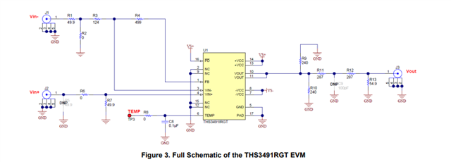
I recently used this evaluation board to measure the frequency response of THS3491RGT when in A = 10V/V, using a range of Rf and Rg (feedback / gain resistors).
I used an R&S FPC1500 spectrum analyser to measure the frequency response.
I also used a Gw Instek GPS3303 dual power supply power the evaluation board. The outputs of the power supply was set to +15V 0.2A and -15V 0.2A.

I connected the inputs / outputs as follows:
Vin - : No connection
Vin+ : FPC1500 general output (0.2Vpp, variable frequency)
Vs- : -15V 0.2A (from power supply)
Vs+ : 15V 0.2A (from power supply)
Vout : FPC1500 RF input port
GND : to power supply ground.
I have done the following to this board:
1. Replace and install Rf and Rg several times with different values to record the output vs. different feedback resistors
2. Remove and install R7 to record how the termination resistor affects the output
3. Connected
After installing a different set of Rf and Rg, I noticed that on the power supply, Vs- pulls 0.15A and Vs+ pulls 0.1A.
When both Vin- and Vin+ are not connected, pins 10 and 11 measured -10V and pin 1 measured -1V.
I understand that I may have damaged the evaluation board, but I'm hoping if someone here could help suggest some more debugging steps to identify how I damaged it so that I avoid damaging another evaluation board.

