Because of the holidays, TI E2E™ design support forum responses will be delayed from Dec. 25 through Jan. 2. Thank you for your patience.

This thread has been locked.

If you have a related question, please click the "Ask a related question" button in the top right corner. The newly created question will be automatically linked to this question.

OPA4227: Behavior in case of input condition is open

Part Number: OPA4227

Hello,

Let me confirm whether you have ever heard following condition.
Could you confirm below and give me your opinion or comment ?

* My customer use OPA4227.
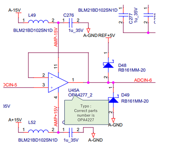
They use 4ch opamp with voltage follower.

However, in their case, sometimes there is the case that one of or multiple opamp input become open. (OPAMP's input come from connector. sometimes one of or multiple opamp's input connector become disconnect.)

In this condition, they saw heating issue on OPAMP (Surface temp become approx 80 degree.)
Customer guess that high current flow to diode in this condition.

However, output load condition is same between input condition is open and normal operation.
So, we wonder why we see this condition only input condition is open...
Do you have any idea ?

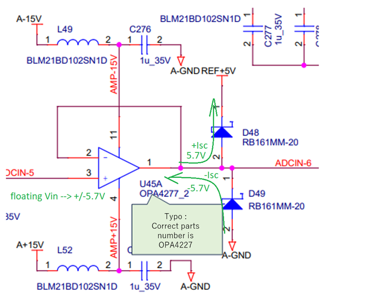
Finally, Here is customer's circuit arround opamp.
If you have any question about condition, please let me know.

Best Regards,

  • Disconnecting the input of the follower will result in the non-inverting input moving either up or down - this depends on the polarity of the input bias current (IB). This movement will continue until the output diodes will clamp the output within the diode drop (~0.7V) of +/-5V. Under such condition the output will sink or source short-circuit current (+/-45mA) trying to move the output further towards one of its rail (+/-15V). This causes output dissipation inside the op amp: Pdiss = (15V-5.7V)*0.045A = 0.42W per channel, heating up the package.

  • Hello,

    Thank you for your reply.
    I have one question.

    * You describe "-5.7V" at diode "D49".
    However, this diode connect to GND not "-5V" negative voltage.
    In that case, do "-5.7V" appear if amp behave sink ?

    Best Regards,

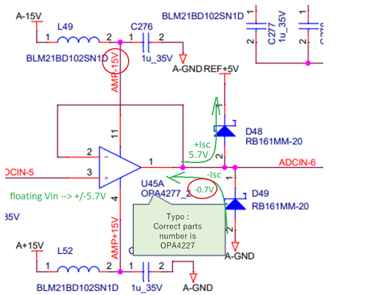
  • Correct - see diagram below.

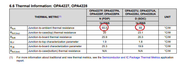
    With D49 connected to ground and IB coming out of the non-inverting input, the input will move downward until the D49 diode will clamp the output around -0.7V below ground.  Thus, while sinking the current the power dissipation inside the op amp will be even higher: Pdiss_SC(short-circuit) = (15V-0.7V)*0.045A = 0.644W.  Please note that this is in addition to the power dissipation due to quiescent current:  Pdiss_IQ = (4*0.0037*30V) = 0.444W.  Thus, assuming ambient room temperature and junction-to-ambient thermal resistance of 65C/W (see below), the junction temperature of OPA4227 may increase to: Tj = 25C+(0.644W+0.444W)*65[C/W] = 25C+70.7C = 95.7deg C

  • Hello,

    Thank you for your reply.
    Is my understanding which one I should apply is depend on ibias current correct ?

    *Pdiss_SC(short-circuit) = (15V-0.7V)*0.045A = 0.644W.  
    *Pdiss = (15V-5.7V)*0.045A = 0.42W

    Is it possiblity that ibias polarity vary between each channel ?

    Best Regards,


  • This is correct.  Due to the fact that OPA4227 includes internal input bias current cancellation circuitry, its IB input bias current may have different polarity between each channel resulting in output being driven to either 5.7V or -0.7V;  this would result in different power dissipation. 

  • Hello,

    Thank you for your reply.
    To avoid useless power dissipation, I understand user should avoid open state for input. However if you have any solution to avoid this if input state become open unintentionally, could you tell it to me ?

    Best Regards,

  • The simplest solution would be to add a large (e.g. 1Mohm) resistor between the input and system ground so under normal condition the 1Mohm can be easily driven by the input signal (has no negative effect) while under open condition it keeps the input and thus output around 0V preventing turning-on of D48 and/or D49 clamping diodes.

  • Hello,

    Thank you for your reply.
    I understood that large (1Mohm) resistor is used to let bias current go to GND because current schematic do not have path which bias current go away.
    Thank you for your explanation.

    BR,