Other Parts Discussed in Thread: LM339B, LM393B
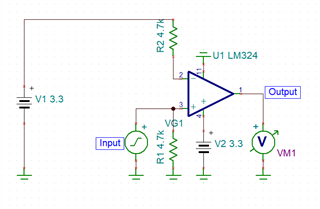
I am troubleshooting this circuit designed by another company.
The LM324B is powered from 3.3V.
The input voltage is to be specified between 9-36V with low source impedance.
The output is expected to be essentially a "clipped" version of the input voltage, limited by the LM324B voltage rail. With no feedback, it is expected to be essentially a digital output ie high/low.

Only around 10/20 of these circuits work from a PCB production run while all other functions on the board work correctly. I wouldn't expect this many failures to be assembly related.
My expectation was the input voltage being so far outside the power supply rails was damaging the LM324B.
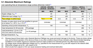
Looking at the datasheet (section 5.1, line 3), the absolute maximum input voltage on the input pins is listed as -0.3 to 40V.

It does not say if this is power-rail dependant or not. I would, therefore, have to assume it is not. Which would mean there is no design problem from this perspective.
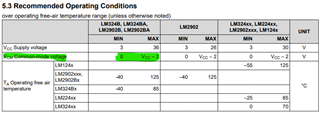
When the input voltage is above 1.3V, we exceed the recommended common mode voltage range as shown below.

Is that the problem?
Any thoughts are appreciated.

