This thread has been locked.

If you have a related question, please click the "Ask a related question" button in the top right corner. The newly created question will be automatically linked to this question.

OPA2241: OPA2241_HPF_Design_Duplication

Part Number: OPA2241
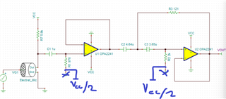
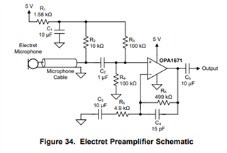
Other Parts Discussed in Thread: OPA1671, OPA172

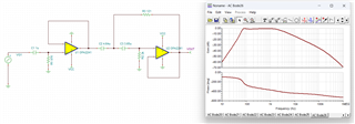
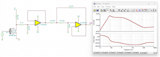
I'm designing a HPF for reducing the hum noise in audio signals

Even though OPA2241 has 2 internal opamp, the filter tool showing 2 seperate quantities of OPA2241 so getting confused.Can anyone please review it once? Attached the design filter report. 

filter-design-report-18.pdf

  • Hi Santhosh,

    Yes this is confusing.  The BOM should not list 2 devices; you will only need 1 device, and the filter will use both amplifiers on the single device.  We'll keep this in mind for future revisions.

    Regards,
    Mike

  • Hi , Thanks for the quicl response. 

    I'm trying to integrate one high pass filter with the following cut-off frequencies:

    1. Stopband:60dB(To reduce humming noise from AC switching freq)

    2. Passband:80dB(Voice range starts from 85dB so don't wanna clip any noise)

    3. Attenuation in stopband & passband:Prefably -4dB and preferably 0dB. 

    During simulation in TI design tool & in TINA, the overall frequency response came fine but when I integrated with electret microphone(I followed this: https://www.ti.com/lit/ug/tidu765/tidu765.pdf?ts=1702294147029&ref_url=https%253A%252F%252Fwww.google.com%252F) , the overall response completely varied. 

    Can you help me with optimising the values so as to get the desired response with electret micrphone?

    Also, while designing in TI design tool(Browser), it's considering frequency response till 1k but I wanted to extend the HPF performance till 20khz! Is there any knob that I need to tweak for extending the frequency range?

  • Santhosh,

    1. Can you please attach your TINA schematic?   Specifically, I do not have the electret microphone model.  Regarding the response. 
    2. The OPA2241 has a gain-bandwidth product of 35kHz.  This is a pretty low bandwidth if you are trying to achieve 20kHz bandwidth.  Is this a very low power application?  That is the main reason you would consider using a low power / low bandwidth amplifier.  If you really need low power this amp may work, but I want to check.
    3. Usually when you design an active filter, you want to take care to keep the capacitor values low.  Ideally, you would use C0G capacitors for distortion purposes, and the maximum C0G value available is 0.1uF.  Also, you don't want to connect large capacitance directly to the output of an op amp (or through a small value resistor).  The 121 and 3.6uF capacitors in your circuit introduce a little gain peaking. I adjusted the value of the capacitor to resistor ratio in your circuit. See below.
    4. Once you send me the TINA (including the electret microphone mode).  I can refine this further.

    origional values.TSC

    re-design filter.TSC

    Best regards, Art

  • Hi Santhosh,

    You have this amp. stuck in the low supply rail.  In order for this to work at all, the DC bias nodes need to be in a place were the amp. can operate in the linear region -

    We do have several electret mic. designs available on ti.com.  The OPA1671 data sheet also has an electret mic. design that will add 40 dB of gain, as well.

    https://www.ti.com/lit/ds/symlink/opa1671.pdf

    Hope this helps,
    Mike

  • Hi , Thanks a lot for your detailed explanation. 

    I've attached one TIA microphone amplifier circuit that's from TI & it has electret microphone. I don't know how to extract that particular macro & share it so...

    SBOA291.TSC

    We've one LPF filter on the other board(OPA172) from where the signal comes. We thought of bypass this circuit but it may help you in getting a better frequency response. 

    Hum filter design - autosave 23-12-13 11_11.TSC

    #With electret micrphone, the overall frequency response becomes something else!

  • Kumar,

    Thanks for the extra detail.  I looked at your original post and see that you want to attenuate "humming noise".  I assume you mean 50Hz or 60Hz.  So, I added a High Pass Filter with a cutoff at 100Hz.  This doesn't provide a lot of attenuation at 60Hz, but it does help.  To get substantial attenuation at 60Hz you would need to move up the cutoff frequency, but for audio you probably don't want to move it too high or you are loosing some audible bandwidth.  I added a gain of 11V/V.  You mentioned "80dB" pass band but I don't think you want 80dB of voltage gain in the pass band as this is a very high gain (10,000V/V of gain).  By the way I agree with Mike that the original circuit needed the DC bias and it looks like you added this.  I hope this simulation helps.  If not, can you draw the curve your are expecting.  

    hpf second stage fc 100Hz g 11.TSC

    Best regards, Art