Because of the holidays, TI E2E™ design support forum responses will be delayed from Dec. 25 through Jan. 2. Thank you for your patience.

This thread has been locked.

If you have a related question, please click the "Ask a related question" button in the top right corner. The newly created question will be automatically linked to this question.

OPA189: Transients during current limiting; Expected behavior

Part Number: OPA189
Other Parts Discussed in Thread: OPA192, OPA205

Hello –

I’m working on a design using the OPA189 where from time to time the output may unintentionally get loaded down aggressively, taking the OPA189 into its current limit. I’ve run into some issues where I see transient spikes (on all nodes, V+,V-,Vout) as the device enters and exits that overcurrent state. Is this a byproduct of the chopper blocks internal to the OP189? Related to section 8.3.3 of the datasheet, Input Bias Current Clock Feedthrough?

Just so I’m clear with a direct question – what is the expected behavior of the OP189 when it’s taken into it’s current limit? When it enters or exits from a shorted output condition?

I don’t see these transient spikes when I simulate the same network and conditions using the OPA192. Is there another amplifier that could be recommended? I’d like to have a network that is able to withstand a shorted output, with minimal additional spiking transients if possible.

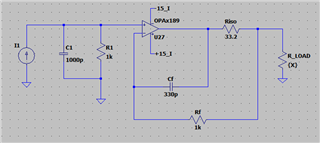
My design is similar to this –
  • Andrew,

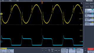
    The chopping transients are basically sharp current spikes that occur on the input at the chopping frequency and harmonics.  For the OPA189 the lowest chopping transient you should see is approximately 135kHz.  I think you are measuring 23kHz, but the picture is a little blurry so I'm not sure.  In any case, the transients are aggravated by larger source and feedback impedances.  For the OPA189, a 1kΩ should is a reasonable impedance.  Also the level of the transients is quite small compared to what you show.  Your transients are a couple volts in amplitude (they should be milivolts in amplitude).  Finally, the transients are not really related to the amplifier current limit.

    To help understand the problem better, can you explain the two waveforms?  Where is each waveform measured?  I think the yellow waveform is the amplifier output but I don't know what the blue waveform (square wave) is.  When you drive an amplifier into current limit will require some time for recovery (i.e. the amplifier output is saturated in current limit).  Output current limit and overload recovery is covered in sboa583).

    Understanding the nature of the overload condition will help us to answer your question better.

    Best regards, Art

  • Hi Art - 

    Thanks for your response. 

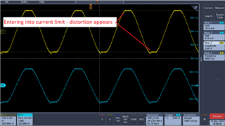
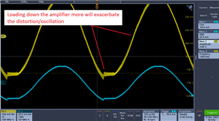
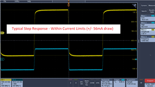
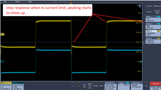
    The yellow waveform is the amplifier output, and the blue waveform is the output current of the amplifier, measured with a TCP0030A Tek current probe. The peaking of the blue waveform, I believe, is the probe trying to keep up with the noisy voltage transient that corresponds to the spike in the yellow waveform. We can see that the spike on the yellow waveforms occur when the amp current enters/leaves the current limit of the op amp (seen in the blue waveform, 60mA range, typical). 

    So that is the issue I'm trying to resolve here. When the OP189 is taken to it's current limit, it shows signs of instability. When I look at a step response of the amplifier network as it's operating in normal conditions, the compensation seems good. Ultimately I was trying to gauge whether it would be a good idea to adjust the compensation elements in the design, or move to an alternative amplifier (like the OPA192) to avoid the changes in behavior when the amplifier entered into an overloaded state. 

    I do acknowledge it would just be good to avoid overloading the amplifier - but there may be use cases where we can't get around that, and would like to make sure the operation of the amplifier was as "well behaved" as possible during that time.

    Here are some other scope shots showing the amplifier going into it's current limit and the corresponding distortion/instability. Again, yellow is the amplifier output and blue is the current output. 

  • Andrew,

    Thanks for the additional detail.  This is really helpful.  

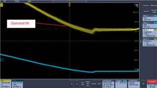
    1. When I look at the step response, I estimate about 35% overshoot which translates to a phase margin of 35deg.  We normally recommend 45deg of phase margin.  So, I agree that this looks marginally stable or somewhat unstable.  Your zoomed in graph is also very informative and shows what looks like a continuous low level oscillation. 
    2. Instability is normally caused by capacitive load or capacitance on the inverting input with respect to ground.  I don't see this in your schematic.  I wonder if there is something in the actual circuit not shown in the schematic.
    3. It is easiest to stabilize circuits with flat output impedance vs frequency.  One disadvantage of chopper amplifiers is that they generally have non-flat output impedance.  Figure 7-25 in the OPA189 data sheet show the output impedance vs frequency.  This is definitely not flat.  The OPA192 is relatively flat (note that the hump at low frequency isn't generally a stability issue).  Maybe the main chopper related issue is simply that the output impedance is not flat and the stability is not great for your conditions.
    4. A step change in output current is actually the same as a step change on the input from a stability perspective.  So, when a device is marginally stable and the output current makes a step change you will see overshoot and ringing.  In your case, the zoomed in waveform indicates that there is a low-level continuous oscillation.    
    5. Based on the schematic I don't see the source of the stability issue.  I think something is likely missing from the schematic.  The circuit looks like an Riso-dual-feedback configuration which is designed to drive capacitive load, but I don't see the capacitive load.  We can simulate and adjust component values for optimal stability.  I did a quick TINA simulation and didn't see any issue (as expected).
    6. I think it is likely that switching to OPA192 or OPA205 the stability issue would go away.  These types of devices have a flatter output impedance, so are generally more robust from a stability perspective.  However, it is probably a good idea to identify what the source if the problem is and I don't see it on the schematic.  Can you provide a full schematic?
    7. If you disconnect the op amp load does the low level continuous oscillation go away?

    Thanks again for all your detailed measurement.  I hope this feedback is helpful to you.

    Best regards, Art