This thread has been locked.

If you have a related question, please click the "Ask a related question" button in the top right corner. The newly created question will be automatically linked to this question.

INA293-Q1: Current Sense Waveform Different - Noise Problems

Part Number: INA293-Q1

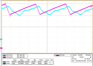
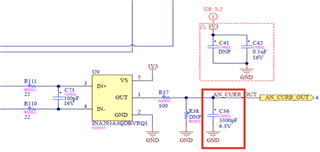
We have a simple current sense circuit and we measure the current from a 2 mOhm sense resistor from a high side of 28 Vdc. 

Current to be measured is inductor current which has a switching frequency of 300 kHz. 

Below CH2: Voltage of C36 (current sense amplifier output)

CH3: Inductor Current (measured by current probe)

Is this normal behaviour? C36 is connected to the DSP ADC input. 

Thanks
  • Hello CY,

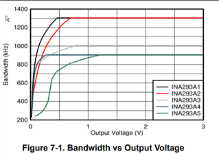
    I do not expect the behavior completely but some of it.  There will be a rounding of the sharp edges transitions as this is beyond the bandwidth.  Also on the lower sides I do expect slower behavior as our bandwidth does change with output voltage as seen in the datasheet.(I have attached screen shot below) 

    Another think to consider is your VCM change.  Is your common mode voltage switching at the input causing another error source that is getting filtered out with your RC and looks like a longer high time?

    Our INA296 is faster and does not depend on the Vout.  This may be an option.

    Out INA241 has better PWM rejection but will not work at 300kHz as this will have issues with rejecting every pulse.  If VCM is not changing at the input then I would use the INA296.

    Regards,

    Javier