Other Parts Discussed in Thread: OPA192
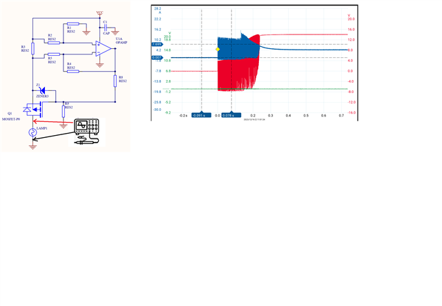
OPA2192 is designed for current detection. When 100nF is added to C1, it is found that the output causes oscillation. Is there any need to correct this circuit?
This thread has been locked.
If you have a related question, please click the "Ask a related question" button in the top right corner. The newly created question will be automatically linked to this question.
Hi Angus,
When 100nF is added to C1, it is found that the output causes oscillation.
Adding the bypass capacitor, C1, should not result in output oscillation. The oscillation is likely caused by something else, but I can only speculate at the moment, since you did not provide any details.

Please try out the following modification and re-measurement.
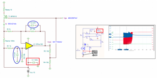
a. add C2 and C3 of 22nF capacitor to the difference amplifier as shown above, which it will limit the BW of the OPA192 for the current sensing application.
b. Limit the scope's BW to 20MHz or lowest BW setting in the scope.
c. Keep the tip of scope leads as short as possible, and insert a 100Ω resistor in series with tip of the voltage probe.
I am not sure if OPA192's Vcc is powered by a switching regulator. If it does, please use low ESR 1uF-4.7uF MLCC ceramic bypass capacitor to reduce the switching noises. This may be the noise source from the Vcc power source.
Please use the matching resistors for OPA192 difference amplifier (use 1% or better tolerance resistors to construct the difference amplier).
If you have other questions, please let me know.
Best,
Raymond