


Part Number: TLV9002
Dear team,
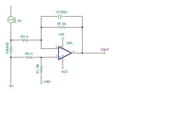
For a typical low-side current sampling application as shown in the figure, CF and RF are usually used to set up a low-pass filter to filter out unnecessary low-frequency noise, and at the same time set a -3dB closed-loop bandwidth.
But in fact, since the GBW of OPA is not infinite, it is usually suggested that the GBW/(1+RF/RG) of OPA is several times more than 1/2pi*CF*RF. Is there any material that analyzes the theoretical basis and mathematical calculation process? I want to manually calculate what the corresponding closed-loop -3dB bandwidth will be under this circuit, assuming that I choose GBW not large enough.
For example: For the circuit in the picture, assuming that the input and output of the OPA are within the range of the specification, and the GBW selected for the op amp at this time is 1MHz (similar to TLV9002), what will the closed-loop -3dB bandwidth of the following circuit? Can you give me the calculation process, not just the empirical values and simulation results?

Best regards
Wesley
